Effectivity 912/914 Series
Edition 1 / Rev. 0
75-00-00
page 13
May 01/2007
d02625
BRP-Rotax
Maintenance Manual
3.9) Ignition housing assembly
See 72-00-00 sec. 3.5.
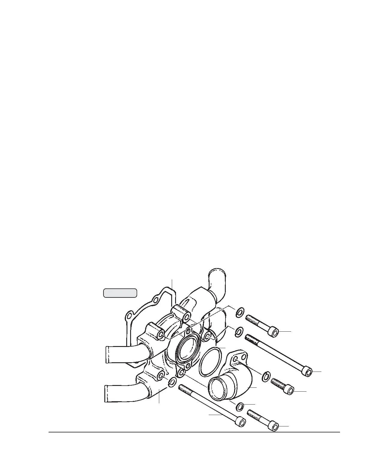
3.10) Water pump housing — reassembly
See Fig. 75-11.
Position gasket (1), attach water pump housing (2) to the ignition housing with
2 allen screws (3) M6x90 and 3 allen screws (4) M6x35 together with lock
washers, torque to 10 Nm (90 in.lb).
■ CAUTION : The bottom allen screw (5) M6x35 protrudes into the water
chamber, so it is of stainless steel and fitted with a sealing ring
(6).
Carry out a visual inspection to see whether the impeller scuffs in the pump
housing. This can be recognized by scuffing traces in the pump housing or on
the impeller. If necessary, the axial position of the water pump impeller can be
corrected to achieve an optimum gap, see 75-00-00 sec. 3.8.
Insert O-ring (7) into water pump housing, fit the water inlet elbow (8) in the
position marked before disassembly with 2 allen screws (9) M6x20 with lock
washers. Tightening torque 10 Nm (90 in.lb).
◆ NOTE: The water inlet elbow is symmetrical and can, if required, be
fitted in other positions.
00392
6
7
8
9
1
3
4
5
3
2
Fig. 75-11