BRP-Rotax
Maintenance Manual
72-00-00
page 16
May 01/2007
Effectivity 912/914 Series
Edition 1 / Rev. 0
d02622
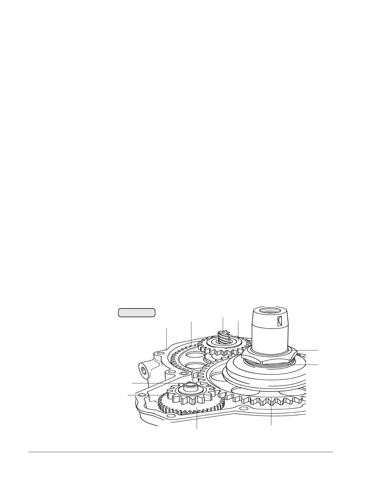
3.6.1) Sprag clutch removal
See Fig. 72-11.
Lock the crankshaft. See the latest issue Maintenance Manual (Line
Maintenance) for the respective engine type, 912 Series or 914 Series.
Pull out the intermediate gear shaft (1) and remove the intermediate
starter gear (2) with the thrust washers 12.5/21.5/1 (3) on both sides
of the intermediate gear.
Unscrew the hex. nut (4) M34x1.5 from the crankshaft using socket
wrench a/f 46, part no. 877450.
◆ NOTE: The hex. nut (4) has a lefthanded thread!
Insert protection piece, part no. 877410, into the crankshaft and
remove the sprag clutch housing (5) from the crankshaft with puller,
part no. 877375.
The free wheel gear (6), the pump gear (10) pressed onto the camshaft
and the timing gear (8) underneath it can be removed only after splitting
the crankcase.
◆ NOTE: The mechanical rev counter is driven via the worm gear
(7) pressed into the camshaft.
◆ NOTE: The worm gear (7) is optional on newer engine ver-
sions.
00236
8
9
7
1
2
3
4
5
6
Fig. 72-11
10