66
CONTROL UNIT
10
Replacing the Volume
1
Switchotheunit.
2
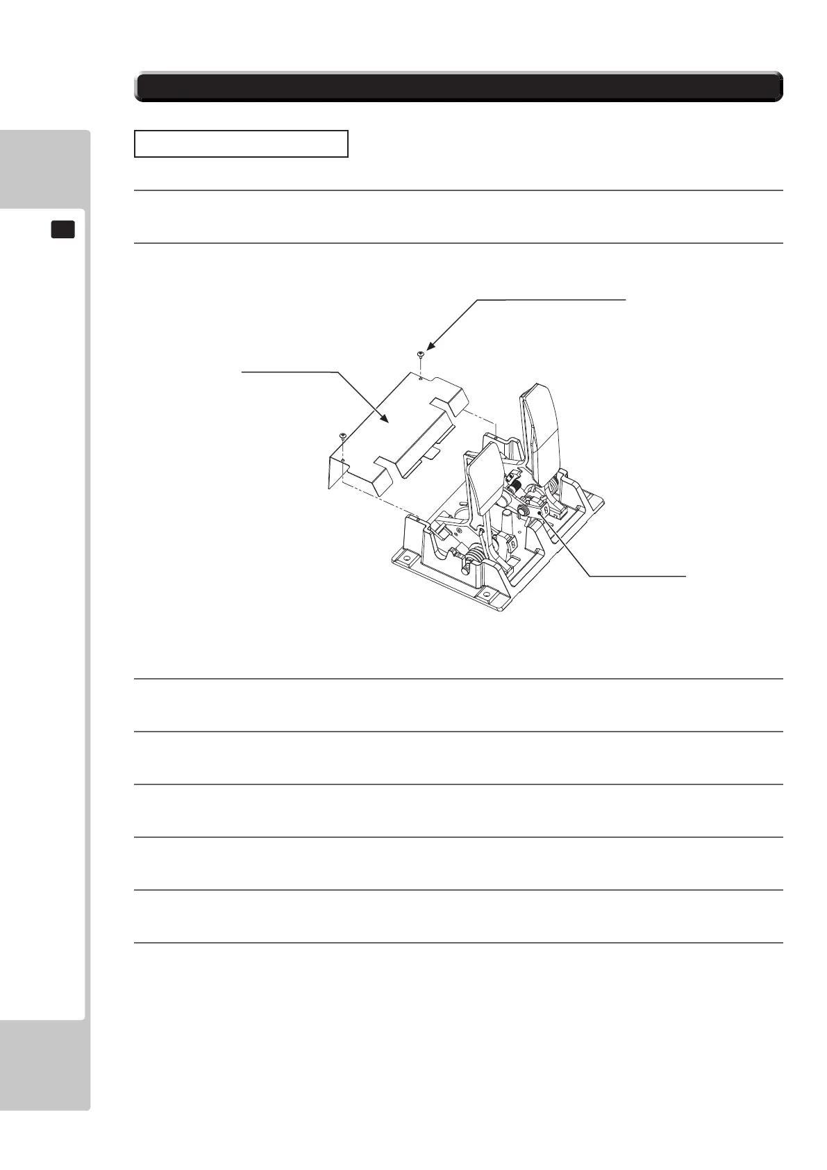
Removethetwoscrewsandliftothepotentiocover
.
10-3-1FIG.0
1
3
Detachtheconnectorfromthevolumetobereplaced.
4
Removethesinglescrewthatsecuresthepotentiobase.(see10-31FIG.02).
5
Withoutdetachingthevolume,removethepotentiobase.(see10-31FIG.03).
6
Removethebaseandgearfromthevolume,andreplaceit.
7
Afterreplacement,congurethevolumeasdescribedabovein“AdjustingProcedure”
8
Whenyouhavenished,checkthatthevalueschangesmoothlyinresponsetopedalinput.
TRUSS SCREW (2), chrome
M4x8
POTENTIO COVER
POTENTIOBASE
10-3-1 ADJUSTING/REPLACING THE VOLUME POT

 Loading...