8.5 Replacing the connectivity module
8.5.1 Replacing the connectivity module (hardware)
Connectivity module as a spare part
You can order the connectivity module as a spare part (Page 204). The battery is not connected
and it has no motor parameters. You must congure the device from new.
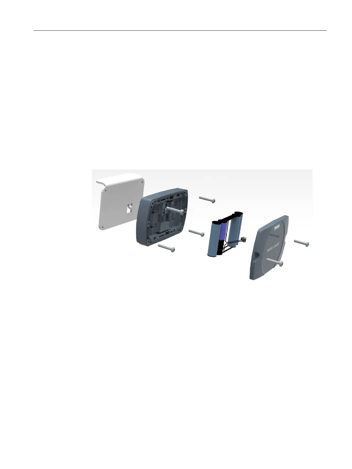
Procedure
1. At the front cover release the two central fastening screws.
To avoid losing the screws, do not turn the screws completely out of the cover.
2. Remove the front cover.
3. Withdraw the battery connector.
4. Release the 4 fastening screws that x the connectivity module to the holder.
5. Remove the connectivity module from the mounting bracket.
6. Place the new connectivity module in the mounting bracket.
7. Retighten the 4 fastening screws.
8. Insert the battery connector.
9. Put the front cover back in position. Ensure that the cover ts precisely.
10.Tighten the 2 central fastening screws at the front cover by hand.
11.Recongure the connectivity module (Page37).
Maintenance
8.5Replacing the connectivity module
SIMOTICS CONNECT 400
Operating Instructions, 04/2023, A5E50161952B AL 139
 Loading...


