Home
Siemens
Control Unit
SINUMERIK 802D
Siemens SINUMERIK 802D Training Manual
5
of 1
of 1 rating
212 pages
Give review
Manual
Specs
To Next Page
To Next Page
To Previous Page
To Previous Page
Loading...
Notes
SINUMERIK 802D sl Operating a
nd Service Training Manual
Page 6
C97
C97
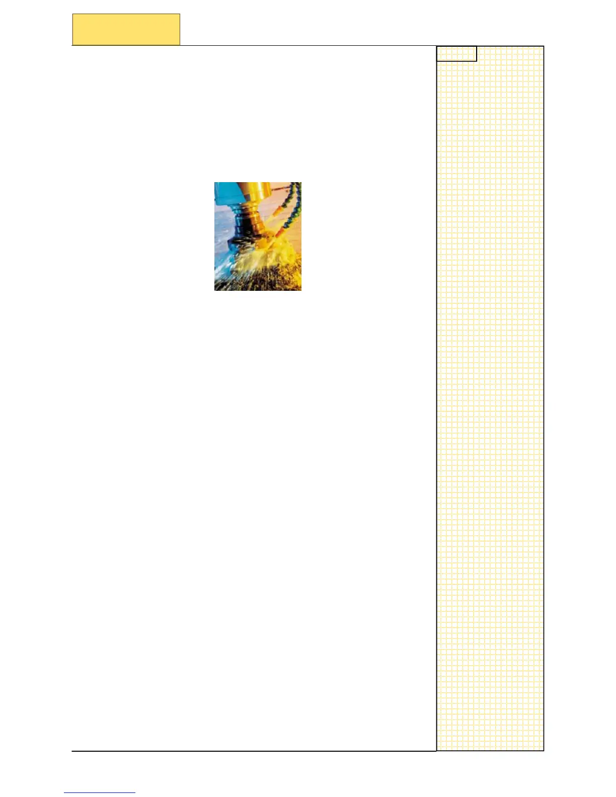
Coolant ON/OFF (M08 - M09)
Function
To switch ON and OFF of coolant system on machine.
Programming
M08
; switch on of coolant system
M09
; switch off of coolant system
——————————————
———————————
————————
Section 3
Miscellaneous functions
35
37
Table of Contents
CNC Basic Principles Milling
7
Brief Description
7
Module Content
7
Fundamentals of CNC Machines
7
Basic Program Structure
9
Basic Structure of NC Program
10
Basic Structure of NC Program for Turning
11
Basic Structure of NC Program for Milling
12
Modality (Preparatory Functions)
13
G Function Overview
14
Modally Valid Motion Commands
15
Non-Modally Valid Motion, Dwell
15
Programmable Frame, Working Area Limitation
15
Plane Selection
15
Tool Radius Compensation
16
Settable Zero Offset
16
Frame Suppression
16
Exact Stop - Continuous-Path Mode
16
Workpiece Measuring Inch/Metric
17
Workpiece Measuring Absolute/Incremental
17
Feed Type
17
Feed Override on Inside and Outside Curvature
17
G Function Window Display
18
Commonly Used G Functions Milling
21
G Functions “Milling” in Detail
22
Linear Interpolation G01
22
Circular Interpolation, G02/G03
22
Dwell Time G4
23
Plane Selection G17
23
Tool Radius Compensation G40
24
Tool Radius Compensation G41
24
Tool Radius Compensation G42
24
Zero Offset G54 to G59
25
Absolute Dimension G90
25
Feed Rate G94
26
Feed Rate G95
26
Exact Stop/Continuous-Path Control: G09, G60, G64
26
Example Contour Program
27
Example Drilling Program
29
Miscellaneous Codes
31
Tool Offset Number D
32
Path Velocity F
33
Spindle Speed S
33
Miscellaneous Functions
34
Program Stop (M00, M01)
34
End of Program, M02, M17, M30
35
Direction of Spindle Rotation (M03 - M04 - M05)
35
Tool Change (M06)
35
Coolant ON/OFF (M08 - M09)
36
T, D, F, S Window Display
37
M and H Window Display
38
Additional G Functions for Milling
39
Additional G Functions in more Detail
40
Rounding, Chamfer - RND, CHF, CHR
40
Angle - ANG
40
Unconditional Program Jumps
41
Conditional Program Jumps
41
Milling on Peripheral Surface - TRACYL
42
Creation of a Milling Program
45
Creating a Work Plan
46
Creating a List of Tools
47
Define the Program Structure
48
End Mill D60Mm
48
Slot Mill D6Mm
48
Create Example Program in Editor
49
Simulate the Program
51
Testing with Simulation
51
Sequence of Operation for Simulation
51
Cycles for Milling
53
Graphical Cycles Support
54
Drilling Cycles
62
Drilling, Centering - CYCLE82
64
Working with CF Cards
71
Brief Description
71
Copying Data to and from the Card
72
Power on and Referencing
75
Switch on the Control
76
Referencing the Axis
77
Axis Control / Jog
79
Jog
80
Jog 1 INC, 10 INC, 100 INC, 1000 INC
81
Jog VAR
82
Control Structure and Navigation
91
Overview of Operating Areas
92
Functionality of the Operating Areas
93
Overview of the Softkeys in JOG
93
Overview of the Softkeys in MDA
93
Overview of the Softkeys in AUTOMATIC
94
Overview of the Softkeys in PROGRAM
94
MDA Milling
95
Functionality of MDA
96
Example Program for MDA
96
Save MDA to Program
97
Face Milling
98
Tools Turning / Milling Functions
101
Working Plane Selection
102
Tool Types for Milling/Drilling G17 Plane
106
Tool Types for Milling G17 & G19 Plane
111
Milling Tool and Workplanes
113
Tool Geometry and Workplanes
114
Tool Offset for Milling Tools
115
New Milling Tool
116
Tool Setting on the Machine
117
Measuring Mode Selection
118
Drilling Tools
119
Work Offsets Milling
121
Overview of the Coordinate System
122
Description of the Zero Offset
122
Description of the Single Components
122
Machine Coordinate System (MCS)
122
Basic Coordinate System (BCS)
123
Wokpiece Coordinate System (WCS)
123
Zero Offset Page in the Control
125
Setting the Zero Offset
127
Automatic
129
Select Part Program
130
Starting a Program
132
RCS802 Data Transfer Tool
133
Principle of Operation RCS802
134
RS232C Online Connection
134
Configure Interface on the Control
135
ISO Dialect Programming for Milling
139
Introduction to ISO Dialect
140
Siemens Mode
140
ISO Dialect Mode
140
Switch over
141
ISO Dialect Milling Addresses
143
Milling G Codes
144
Tool Length Offset (G43, G44, G49)
145
Return Value (G98, G99)
145
Advanced Level Commands
146
Canned Cycles (G73 to G89)
146
Subprogram Call up Function (M98, M99)
147
Basic ISO Dialect Program
148
Mold & die Functionality and Programming
149
List of G Codes
151
Recommended Function
151
Preprocessing Memory Control
151
Soft Smoothed Path Acceleration
152
Feed Forward Control on
153
Recommended Function : COMPCAD
154
Freeform Surface
155
Transfer and Copy a Program
156
Edit a Program
157
Execute a Program
158
Program Roughing
159
Program Header
159
Program Finishing
160
LED Diagnosis HMI
161
Locating the Status Led's
162
Status of CNC Controller Led's
162
MCPA Signal Tests
163
Identification of MCPA in the System
164
Analogue Spindle Interface Test
164
Save Data
165
Performing a Data Save
165
Performing a Save Data
166
Restore Saved Data
169
External Data Backup + Restore with CF Card
171
Saving All Data to Compact Flash Card
172
Restoring All Data from Compact Flash Card
175
Diagnose PLC Program
179
Locating the PLC Program Displays
180
Navigating the Displays
181
Navigating the Displays
182
Program Status ON/OFF
184
Searching
185
Cross Referencing
185
Diagnose PLC Alarm
187
Structure of an Alarm
188
Variable Definition
188
Function of Alarm
189
Cross Reference
190
Alarm Structure NC
191
Locate the Alarm Display
192
Editing of NC Machine Data
193
Location of NC Machine Data
194
Setting Password
195
Changing Machine Data + Data Save
195
Drive Diagnostic Parameters
197
Location of Drive Diagnostic Parameters
198
Pushbutton Tests
201
Hardware Identification
202
Identification of MCP Connected to MCPA Interface Module
202
Identification of MCP Connected to PLC Periphery Board
203
General Information Regarding the Machine Control Panel
204
Hardware Interface
204
Hardware Interface—Mcp Pushbutton Test with Periphery Version
205
Hardware Interface - MCP Pushbutton Test with MCPA Version
207
LED Diagnosis—Drive
209
MM Led's, ALM Led´s, SLM Led´s ≥ 16Kw
210
Other manuals for Siemens SINUMERIK 802D
Programming And Operating Manual
399 pages
Short Guide
49 pages
5
Based on 1 rating
Ask a question
Give review
Questions and Answers:
Need help?
Do you have a question about the Siemens SINUMERIK 802D and is the answer not in the manual?
Ask a question
Siemens SINUMERIK 802D Specifications
General
Brand
Siemens
Model
SINUMERIK 802D
Category
Control Unit
Language
English
Related product manuals
Siemens SINUMERIK 808D
48 pages
Siemens SINUMERIK 808D ADVANCED
498 pages
SINUMERIK 808D ADVANCED Series
480 pages
Siemens SINUMERIK 880
291 pages
Siemens SINUMERIK 810D
520 pages
Siemens SINUMERIK 840D
713 pages
Siemens SINUMERIK 840C
291 pages
Siemens SINUMERIK 840Di
552 pages
Siemens SINUMERIK 840Di sl
470 pages
Siemens Sinumerik 840DiE sl
545 pages
Siemens SINUMERIK 828D Series
246 pages
SINUMERIK 840D Simodrive 611 digital
298 pages

 Loading...


