3-10-2. DC Jack
Preparation
1. Remove the cabinet (G) assembly. (Refer to “3-2. Cabinet (G) Assembly”.)
2. Remove the heat sink (GP) assembly. (Refer to “3-3. Heat Sink (GP) Assembly”.)
3. Remove the top cabinet assembly. (Refer to “3-5. Top Cabinet Assembly”.)
4. Remove the EF-1003 board. (Refer to “3-6. EF-1003 Board”.)
5. Remove the IR cabinet assembly. (Refer to “3-7. IR-1009 Board”.)
6. Remove the inner mold (T) assembly. (Refer to “3-8. Inner Mold (T) Assembly”.)
7. Remove the cabinet (R) assembly. (Refer to “3-9-1. Cabinet (R) Assembly”.)
8. Remove the BT panel assembly. (Refer to “3-10-1. BT Panel Assembly”.)
Procedure
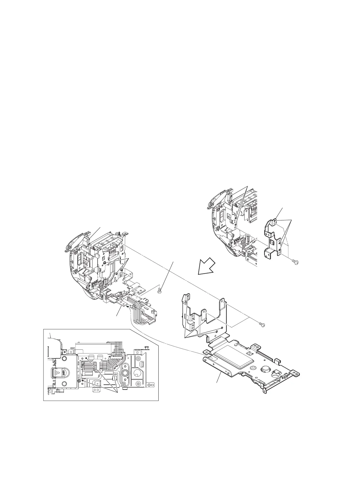
1. Remove the heat sink (BM) assembly.
(1) Remove the three screws (tapping screw (P1.7 x 5)), and then remove the JK frame.
(2) Remove the screw (precision screw (P1.7 x 4)) and two screws (tapping screw (P1.7 x 5)).
(3) Release the seven bosses and hook, and then remove the heat sink (BM) assembly.
Heat sink (BM) assembly
Bottom view
Hook
Holes
Holes
Bosses
Bosses
Bosses
Boss
Precision screw
(P1.7 x 4)
Tapping screws
(P1.7 x 5)
(Tightening torque:
0.14±0.02 N·m)
(Tightening torque
: 0.14±0.02 N·m)
JK frame
HXR-NX80/HXR-MC88
3-34
 Loading...