3-15. Lens Section
3-15-1. Lens Assembly
Preparation
1. Remove the cabinet (G) assembly. (Refer to “3-2. Cabinet (G) Assembly”.)
2. Remove the heat sink (GP) assembly. (Refer to “3-3. Heat Sink (GP) Assembly”.)
3. Remove the GR-1003 board. (Refer to “3-4. GR-1003 Board”.)
4. Remove the top cabinet assembly. (Refer to “3-5. Top Cabinet Assembly”.)
5. Remove the EF-1003 board. (Refer to “3-6. EF-1003 Board”.)
6. Remove the IR-1009 board. (Refer to “3-7. IR-1009 Board”.)
7. Remove the inner mold (T) assembly. (Refer to “3-8. Inner Mold (T) Assembly”.)
8. Remove the cabinet (R) assembly. (Refer to “3-9-1. Cabinet (R) Assembly”.)
9. Remove the BT panel assembly. (Refer to “3-10-1. BT Panel Assembly”.)
10. Remove the ZM-1005 board. (Refer to “3-11. ZM-1005 Board”.)
11. Remove the VF assembly. (Refer to “3-12. VF Assembly”.)
12. Remove the MS-1037 board. (Refer to “3-13. MS-1037 Board”.)
13. Remove the VC-1045 board. (Refer to “3-14. VC-1045 Board”.)
Procedure
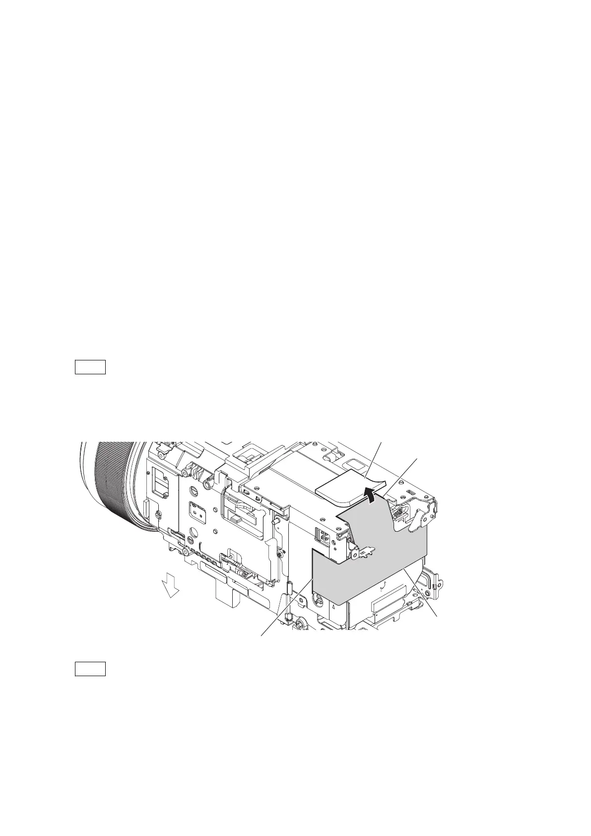
1. Peel off the CM radiation sheet (915).
Note
The CM radiation sheet (915) is not reusable. Prepare new parts in advance.
(1) Turn the the VC radiation sheet (B) as shown in the figure.
(2) Peel off the CM radiation sheet (915).
CM radiation sheet (915)
Scribe line
Scribe line
VC radiation sheet (B)
Lower side
Note
When attaching the CM radiation sheet (915), align it with the scribe lines.
HXR-NX80/HXR-MC88
3-45
 Loading...