VL1500K5 (’05-MODEL) 127
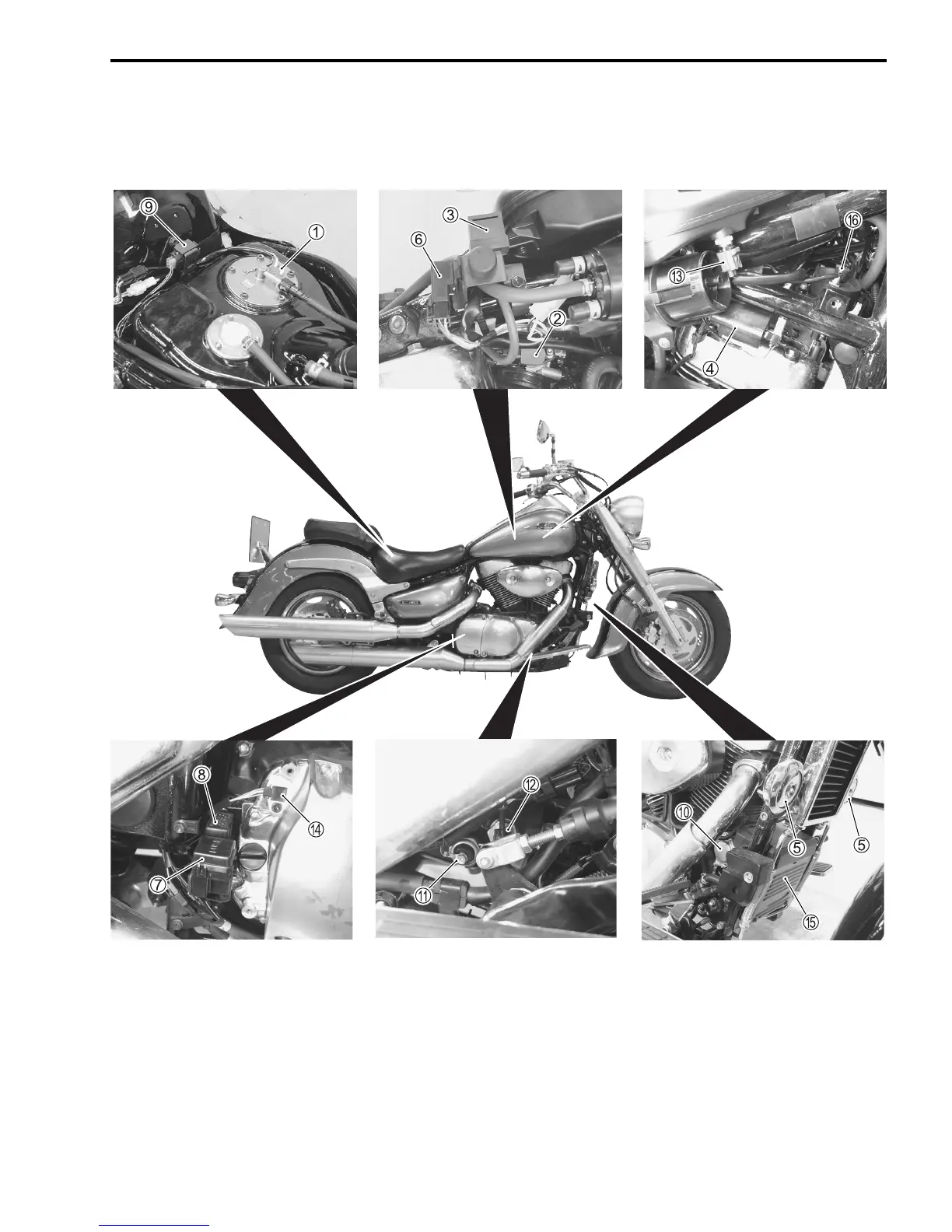
LOCATION OF ELECTRICAL COMPONENTS
1 Fuel pump and level gauge (!Page 95)
9 TO sensor (!Page 70)
2 TP sensor (!Page 53)
0 Starter motor
3 IAP sensor (Front) (!Page 49)
A Oil pressure switch
4 Ignition coil (#2)
B EOT sensor (!Page 58)
5 Horn (**
Except for E-03, 24, 28 and 33)
C IAT sensor (!Page 66)
6 Automatic decompression relay
D Speed sensor (!Page 141)
7 Fuse box
E Battery
8 Side-stand/turn signal relay
F Automatic decompression solenoid
(**): Horn is located under the ECM.
(For E-03, 24, 28 and 33)
SAMPLE
 Loading...