EasyManua.ls Logo

Suzuki VL1500K5 User Manual

Suzuki VL1500K5
181 pages
To Next Page IconTo Next Page
To Previous Page IconTo Previous Page
Page #167 background imageLoading...
Page #167 background image
166 VL1500K5 (’05-MODEL)
SUSPENSION Unit: mm (in)
TIRE PRESSURE
FUEL + OIL
ITEM STANDARD LIMIT
Wheel rim size Front 16 × MT3.50, 16M/C × MT3.50 —
Rear 15M/C × MT5.00 —
Tire size Front 150/80-16 71H, 150/80-16M/C 71H —
Rear 180/70-15M/C 76H —
Tire tread depth
Front —
1.6
(0.06)
Rear —
2.0
(0.08)
ITEM STANDARD LIMIT NOTE
Front fork stroke 140
(5.5)
—
Front fork spring free length
* 601.5
(23.68)
* 589
(23.2)
Front fork oil level
*192
(7.56)
—
Rear shock absorber spring
set length
222.0
(8.74)
—
Rear wheel travel 118
(4.6)
—
COLD INFLATION
TIRE PRESSURE
SOLO RIDING DUAL RIDING
kPa kgf/cm
2
psi kPa kgf/cm
2
psi
FRONT 200 2.00 29 200 2.00 29
REAR 250 2.50 36 250 2.50 36
ITEM SPECIFICATION LIMIT
Fuel type Use only unleaded gasoline of at least 87 pump
octane (R/2 + M/2) or 91 octane or higher rated by
the research method. Gasoline containing MTBE
(Methyl Tertiary Butyl Ether), less than 10% etha-
nol, or less than 5% methanol with appropriate
cosolvents and corrosion inhibitor is permissible.
E-03, 28, 33
Gasoline used should be graded 91 octane or
higher. An unleaded gasoline is recommended.
The others
Fuel tank
* 14.0 L
(3.7/3.1 US/Imp gal)
Engine oil type SAE 10W-40, API SF or SG
Engine oil capacity
Change
3 700 ml
(3.9/3.3 US/lmp qt)
Filter
change
4 300 ml
(4.5/3.8 US/lmp qt)
Overhaul
5 000 ml
(5.3/4.4 US/lmp qt)
Front fork oil type SUZUKI FORK OIL SS-08 (#10) or
equivalent fork oil
SAMPLE

Table of Contents

Question and Answer IconNeed help?

Do you have a question about the Suzuki VL1500K5 and is the answer not in the manual?

Suzuki VL1500K5 Specifications

General IconGeneral
ModelVL1500K5
Year2005
CategoryCruiser
Displacement1462 cc
Compression Ratio9.5:1
Fuel SystemFuel injection
LubricationWet sump
StarterElectric
Transmission5-speed
Final DriveShaft
Rear BrakesSingle hydraulic disc
Engine TypeV-twin
IgnitionDigital electronic
Front SuspensionTelescopic
Rear SuspensionSwingarm
Front BrakesDual hydraulic discs
Front Tire Size150/80-16
Overall Height1145 mm (45.1 inches)
Seat Height700 mm (27.6 inches)
Fuel Capacity18.0 L (4.8 US gal)
Bore x Stroke96.0mm x 101.0mm
Rear Tire Size180/70-15

Summary

ABBREVIATIONS USED IN THIS MANUAL

SPECIFICATIONS

DIMENSIONS AND DRY MASS

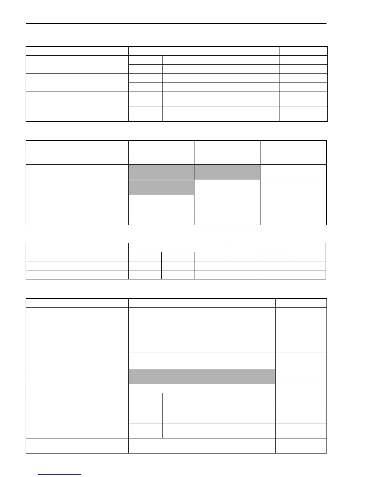
Detailed dimensions and dry mass of the motorcycle.

ENGINE SPECIFICATIONS

Technical specifications for the engine.

DRIVE TRAIN SPECIFICATIONS

Specifications for the drive train components.

CHASSIS SPECIFICATIONS

Specifications for chassis, suspension, brakes, and wheels.

ELECTRICAL SPECIFICATIONS

Specifications for the electrical system components.

CAPACITIES

Capacities for fuel tank, engine oil, and final gear oil.

PERIODIC MAINTENANCE SCHEDULE

MAINTENANCE AND TUNE-UP PROCEDURES

FUEL HOSE INSPECTION AND REPLACEMENT

Procedure for inspecting and replacing the fuel hose.

ENGINE IDLE SPEED ADJUSTMENT

Procedure for checking and adjusting engine idle speed.

THROTTLE CABLE PLAY ADJUSTMENT

Procedure for adjusting throttle cable play.

THROTTLE VALVE SYNCHRONIZATION

Periodic inspection and adjustment of throttle valve synchronization.

PAIR (AIR SUPPLY) SYSTEM INSPECTION

Periodic inspection of the PAIR (air supply) system.

EXHAUST AND CHASSIS BOLT TIGHTENING

Tightening procedures for exhaust and chassis bolts and nuts.

ENGINE COMPONENTS REMOVABLE WITH ENGINE IN PLACE

ENGINE LEFT SIDE COMPONENTS

Components on the engine's left side removable with engine in place.

ENGINE RIGHT SIDE COMPONENTS

Components on the engine's right side removable with engine in place.

ENGINE CENTER COMPONENTS

Components in the engine's center removable with engine in place.

ENGINE REMOVAL AND INSTALLATION

ENGINE REMOVAL PROCEDURE

Step-by-step procedure for removing the engine from the frame.

ENGINE INSTALLATION PROCEDURE

Step-by-step procedure for installing the engine into the frame.

ENGINE DISASSEMBLY AND REASSEMBLY

GEAR POSITION SWITCH SERVICE

Procedures for removing and reassembling the gear position switch.

EOT SENSOR SERVICE

Procedures for removing and reassembling the EOT sensor.

ENGINE COMPONENTS INSPECTION AND SERVICING

CAMSHAFT INSPECTION AND SERVICING

Inspection and servicing procedures for the camshaft.

CAMSHAFT WEAR CHECK

Checking for wear on the camshaft.

PRECAUTIONS IN SERVICING

CONNECTOR AND COUPLER HANDLING

Precautions for handling electrical connectors and couplers safely.

FUSE HANDLING PRECAUTIONS

Precautions to follow when dealing with fuses.

ECM AND SENSOR HANDLING PRECAUTIONS

Precautions for handling the ECM and various sensors.

ELECTRICAL CIRCUIT INSPECTION PROCEDURE

OPEN CIRCUIT CHECK PROCEDURE

Procedure for inspecting electrical circuits for open circuits.

CONTINUITY AND VOLTAGE CHECK METHODS

Methods for performing continuity and voltage checks.

SHORT CIRCUIT CHECK PROCEDURE

Procedure for inspecting electrical circuits for short circuits to ground.

USING THE MULTI-CIRCUIT TESTER

TESTER USAGE GUIDELINES

Guidelines and precautions for using the multi-circuit tester.

FI SYSTEM TECHNICAL FEATURES

INJECTION TIME DETERMINATION

Factors that determine fuel injection time.

INJECTION TIME COMPENSATION

Signals used for compensating fuel injection time.

INJECTION STOP CONTROL MECHANISMS

Signals that control fuel injection stop.

FUEL DELIVERY SYSTEM

FI SYSTEM PARTS LOCATION

FI SYSTEM WIRING DIAGRAM

ECM TERMINAL CONFIGURATION

SELF-DIAGNOSIS FUNCTION

USER MODE DIAGNOSTICS

Self-diagnosis function modes and indicators for the user.

DEALER MODE DIAGNOSTICS

Self-diagnosis function mode for dealers.

FAIL-SAFE FUNCTION OVERVIEW

FI SYSTEM TROUBLESHOOTING

CUSTOMER COMPLAINT ANALYSIS

Form for analyzing customer complaints to diagnose issues.

COMMON PROBLEM SYMPTOMS

List of common motorcycle problems and symptoms.

ENVIRONMENTAL AND OPERATING CONDITIONS

Factors influencing problem occurrence.

VISUAL INSPECTION GUIDELINES

Preliminary visual checks before electronic diagnosis.

SELF-DIAGNOSTIC PROCEDURES

Steps for performing self-diagnosis.

SDS DIAGNOSTIC TOOL USAGE

Procedures for using the SDS diagnostic tool.

SDS DIAGNOSIS RESET PROCEDURE

Steps to reset SDS diagnosis data.

SHOW DATA WHEN TROUBLE (DTC DATA)

Displaying and interpreting data during DTC detection.

MALFUNCTION CODE AND DEFECTIVE CONDITION LIST

List of malfunction codes and their corresponding defective conditions.

FUEL SYSTEM

FUEL TANK REMOVAL PROCEDURE

Procedure for removing the fuel tank.

FUEL PRESSURE INSPECTION PROCEDURE

Procedure for inspecting fuel pressure.

FUEL PUMP INSPECTION AND DISCHARGE TEST

Inspecting fuel pump operation and discharge amount.

FUEL PUMP RELAY INSPECTION

Procedure for inspecting the fuel pump relay.

FUEL PUMP ASSEMBLY REMOVAL AND DISASSEMBLY

Procedures for removing and disassembling the fuel pump assembly.

THROTTLE BODY SYSTEM

THROTTLE BODY CONSTRUCTION DIAGRAM

Diagram illustrating the components of the throttle body.

AIR CLEANER BOX REMOVAL PROCEDURE

Procedure for removing the air cleaner box.

THROTTLE BODY REMOVAL AND DISASSEMBLY

Procedures for removing and disassembling the throttle body.

THROTTLE BODY REASSEMBLY AND INSTALLATION

Procedures for reassembling and installing the throttle body.

THROTTLE VALVE SYNCHRONIZATION PROCEDURE

Procedure for synchronizing throttle valves using a vacuum tester.

THROTTLE POSITION SENSOR (TPS) SETTING

Procedure for setting the throttle position sensor.

SENSORS INSPECTION AND SERVICE

INTAKE AIR PRESSURE (IAP) SENSOR SERVICE

Inspect and service the IAP sensor.

THROTTLE POSITION (TP) SENSOR SERVICE

Inspect and service the TP sensor.

SECONDARY THROTTLE POSITION (STP) SENSOR SERVICE

Inspect and service the STP sensor.

CRANKSHAFT POSITION (CKP) SENSOR SERVICE

Inspect and service the CKP sensor.

INTAKE AIR TEMPERATURE (IAT) SENSOR SERVICE

Inspect and service the IAT sensor.

ENGINE OIL TEMPERATURE (EOT) SENSOR SERVICE

Inspect and service the EOT sensor.

TIP-OVER AND HO2 SENSOR INSPECTION

TIP-OVER SENSOR SERVICE

Inspection and service procedures for the tip-over sensor.

HO2 SENSOR INSPECTION (FOR SPECIFIC MODELS)

Inspection procedures for the HO2 sensor on specified models.

EXTERIOR PARTS SERVICE

SEAT REMOVAL AND INSTALLATION

Procedures for removing and installing the motorcycle seats.

FRONT FORK SERVICE

FRONT FORK CONSTRUCTION DIAGRAM

Diagram illustrating the components of the front fork.

FRONT FORK REMOVAL AND DISASSEMBLY

Procedures for removing and disassembling the front fork.

FRONT FORK INSPECTION AND SERVICE

Inspection of fork spring, oil, and reassembly procedures.

LOCATION OF ELECTRICAL COMPONENTS

CHARGING SYSTEM INSPECTION

GENERATOR COIL RESISTANCE AND PERFORMANCE TEST

Measuring generator coil resistance and no-load performance.

REGULATOR/RECTIFIER VOLTAGE TEST

Measuring voltages at the regulator/rectifier terminals.

AUTOMATIC DECOMPRESSION & STARTING SYSTEMS

SIDE-STAND/IGNITION INTERLOCK SYSTEM INSPECTION

Inspecting the side-stand and ignition interlock system components.

GEAR POSITION SWITCH INSPECTION

Inspection procedures for the gear position switch.

IGNITION SYSTEM DIAGNOSIS

IGNITION SYSTEM TROUBLESHOOTING (NO SPARK)

Troubleshooting steps for ignition system faults like no spark.

INSTRUMENTATION SYSTEM SERVICE

SPEEDOMETER FUNCTION AND COMPONENTS

Overview of speedometer, LEDs, and indicators.

SPEEDOMETER REMOVAL, DISASSEMBLY, AND INSPECTION

Procedures for servicing the speedometer unit and its components.

RELAYS AND SWITCHES

FUEL PUMP RELAY INFORMATION

Information regarding the fuel pump relay.

SWITCH CONTINUITY INSPECTION

Inspecting continuity of various switches.

BATTERY SPECIFICATIONS

ROUTING INFORMATION

WIRING HARNESS ROUTING GUIDE

Guide for routing wiring harnesses on the motorcycle.

CABLE AND HOSE ROUTING GUIDE

Guide for routing cables and hoses on the motorcycle.

FRONT BRAKE HOSE ROUTING

Specific routing for the front brake hose.

REAR BRAKE HOSE ROUTING

Specific routing for the rear brake hose.

FUEL SYSTEM HOSE ROUTING

Routing for fuel system hoses.

PAIR (AIR SUPPLY) SYSTEM HOSE ROUTING

Routing for PAIR system hoses.

EXTERIOR PARTS INSTALLATION

METER/FUEL INLET COVER INSTALLATION

Installation of meter and fuel inlet covers.

FRAME UPPER COVER INSTALLATION

Installation of frame upper covers.

FRAME HEAD COVER INSTALLATION

Installation of frame head covers.

GREASE-UP AND PEDAL INSTALLATION

GREASE-UP POINTS IDENTIFICATION

Identification of points requiring grease.

BRAKE PEDAL INSTALLATION PROCEDURE

Procedure for installing the brake pedal.

SPECIAL TOOLS LISTING

TIGHTENING TORQUE SPECIFICATIONS

FI SYSTEM AND INTAKE AIR SYSTEM TORQUES

Tightening torques for FI and intake air system components.

CHASSIS COMPONENT TORQUES

Tightening torques for chassis components.

SERVICE DATA COMPILATION

VALVE AND GUIDE SPECIFICATIONS

Standard and limit values for valve and guide dimensions.

CAMSHAFT AND CYLINDER HEAD SPECIFICATIONS

Service data for camshafts and cylinder heads.

CYLINDER, PISTON, AND PISTON RING SPECIFICATIONS

Service data for cylinder, piston, and rings.

CONNECTING ROD AND CRANKSHAFT SPECIFICATIONS

Service data for conrod and crankshaft components.

OIL PUMP, CLUTCH, AND DRIVE TRAIN SPECIFICATIONS

Service data for oil pump, clutch, and drive train.

FUEL INJECTION SYSTEM SENSOR SPECIFICATIONS

Specifications for FI system sensors, injectors, and pumps.

THROTTLE BODY AND ELECTRICAL SPECIFICATIONS

Specifications for throttle body and electrical components.

LIGHTING AND BRAKE SPECIFICATIONS

Specifications for lighting and brake system components.

WHEEL, SUSPENSION, AND FLUID SPECIFICATIONS

Specifications for wheels, suspension, tire pressure, and fluids.

EMISSION CONTROL SYSTEMS OVERVIEW

FUEL INJECTION SYSTEM EMISSION CONTROL

Description of the fuel injection system for emission control.

CRANKCASE EMISSION CONTROL SYSTEM

Description of the crankcase emission control system.

EXHAUST EMISSION CONTROL (PAIR SYSTEM)

Description of the PAIR system for exhaust emission control.

NOISE EMISSION CONTROL SYSTEM REGULATIONS

PAIR (AIR SUPPLY) SYSTEM INSPECTION AND DIAGRAM

PAIR SYSTEM HOSES AND PIPES INSPECTION

Inspecting PAIR system hoses, pipes, reed valve, and solenoid valve.

PAIR SYSTEM DIAGRAM

Diagram illustrating the PAIR system.

PAIR SYSTEM HOSE ROUTING

Routing of PAIR system hoses.

HEATED OXYGEN SENSOR (HO2S) INSPECTION

WIRING DIAGRAMS

Related product manuals