18. Electrical System
18-18
Switch / Horn
Main switch
Inspection
Remove the front cover and inner cover.
Disconnect the main switch.
Check the following circuit.
terminal
position
BAT1 BAT2 BAT3
LOCK
OFF
ON
Wire color Red Black Black
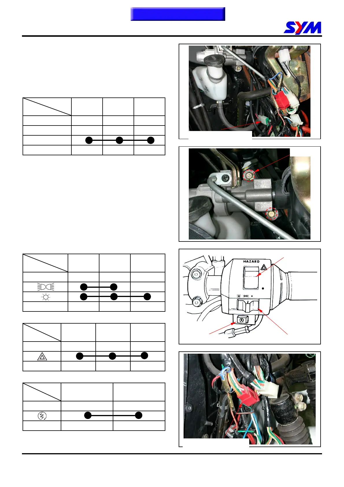
Replacement
Remove the front cover and inner cover.
Disconnect the main switch coupler.
Disconnect the seat-open cable (2 bolts).
Remove the main switch.
Right handlebar switch
Remove the handlebar cover and front cover.
Disconnect the right handlebar switch coupler.
Check the following switch circuit.
Headlight switch
terminal
position
BAT3 TL HL
●
Wire color W / G BR L / W
Hazard light switch
terminal
position
R W L
●
Wire color SB GR
O
Starter switch
terminal
position
ST BAT2
FREE
Wire color Y / R G
Starter switch
Headlight switch
Hazard light switch
Main switch coupler
Right handlebar coupler
2 bolts
To this chapter contents
 Loading...