5
. Fuel Injection System
5-7
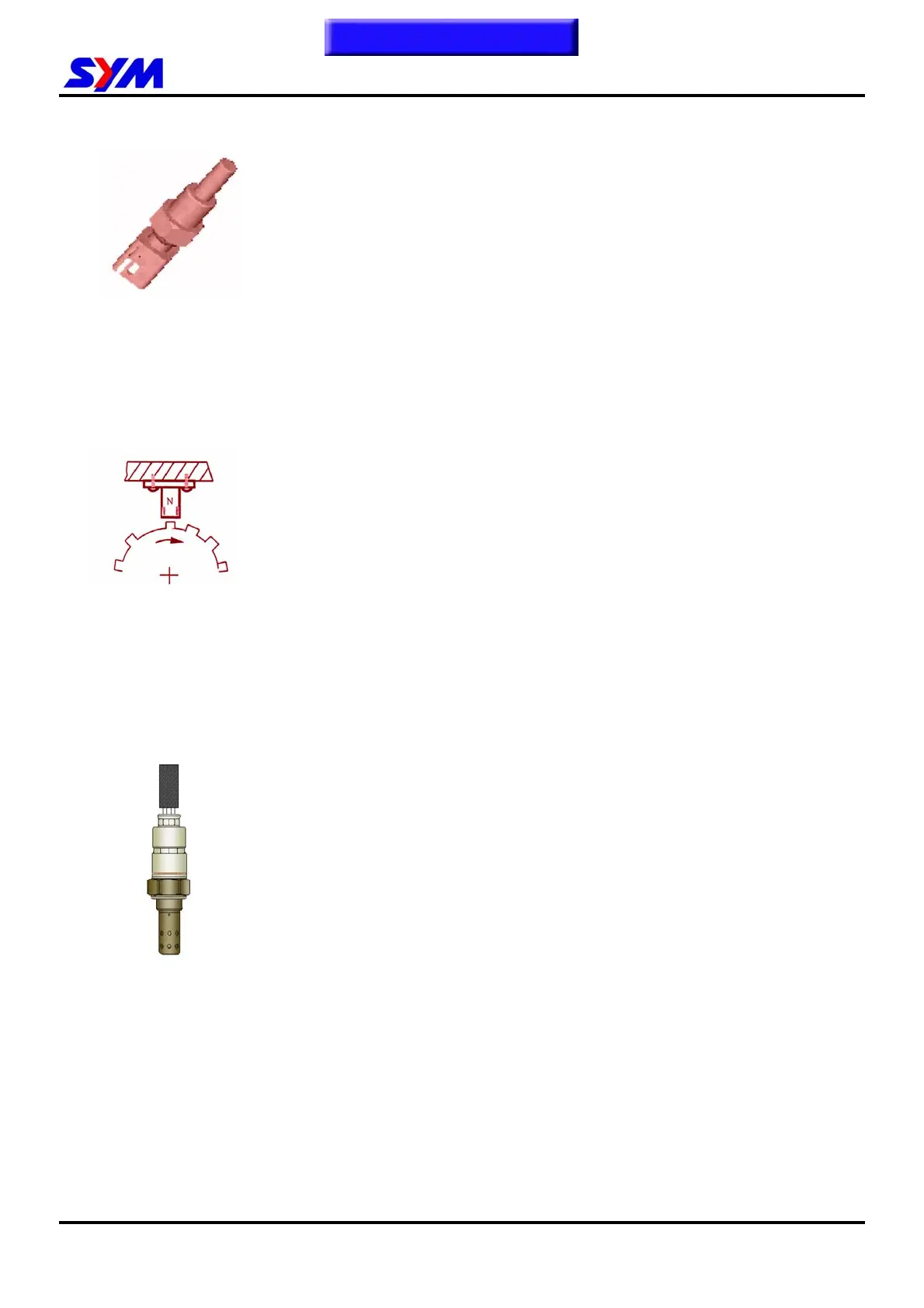
ECT Sensor
• Powered by 5V DC from ECU, and has 2 terminals connector on the
sensor. One terminal is for voltage output and the other one for
ground.
• Its major component is the thermo-resistance of negative
temperature coefficient (temperature rises up while resistance falls
down).
• Located on the cylinder head. Correspondence with engine coolant
temperature change, it transferred to voltage signal and sent to ECU
to calculate current temperature. Then, the ECU will correct fuel
injection time and ignition timing according to engine warm up
condition.
CPS
• It does not need power supply, and has 2-signal terminals connector
on the sensor.
• Its major component is the magnetic pickup coil, and its output
voltage range is ±0.8~100V.
• The air gap between the sensor and flywheel must have .07~1.1mm.
• By cutting the magnetic field, the magnetic sensor sends an
inductive voltage that is created with the rotation gear (24-1 tooth) on
the flywheel, and the pulse will be sent to the ECU. Then, the ECU
calculates current engine speed and crank position based on the
voltage so that controls fuel injection quantity and ignition timing
properly.
O2 Sensor
• Powered by DC 8~16V, and has 4 terminals connector on the sensor.
The first terminal is for power input; the second is for heating coil.
The third is for ground, and the last is for signal output.
• The O2 sensor feeds signal to ECU, and the ECU can control the
air/fuel rate around 14.6. It’s a close –loop control system.
• The catalytic converter reaches the best converting rate when this
14.6 A/F ratio is maintained.
• The heating coil resistance <200kohm (30—45kohm)
To this chapter contents
 Loading...