FUEL SYSTEM Injection Pump FU-53
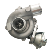
(b) Using a 5 mm hexagon wrench, adjust the protrusion
of the adjusting screw from the timer cover.
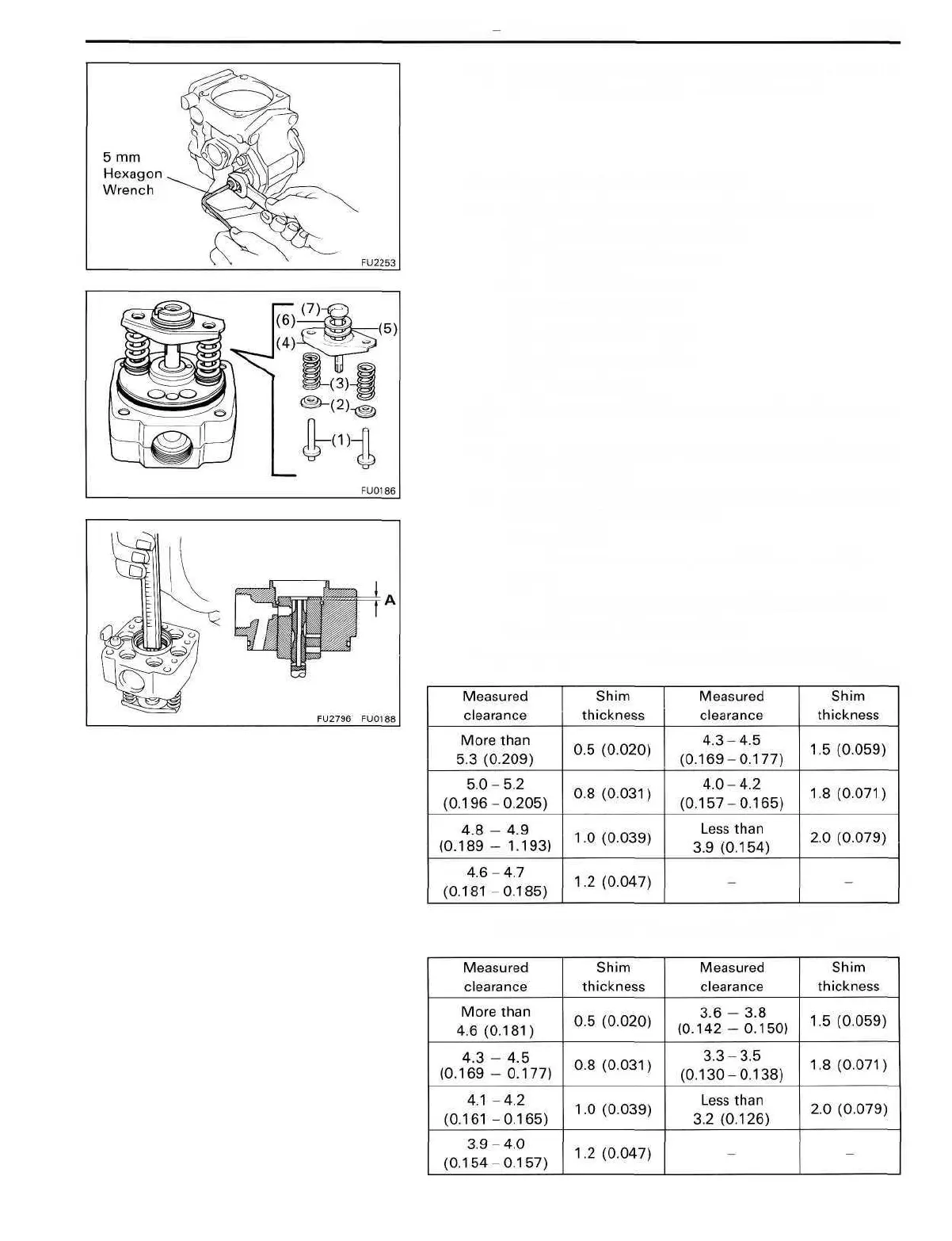
10. ADJUST PLUNGER SPRING SHIM
(a) Install the following parts to the distributive head:
(1) Two plunger spring guides
(2) Two upper spring seats
(3) Two plunger springs
(4) Lower spring seat
(5) Upper plunger plate
(6) Lower plunger plate
(7) Pump plunger
HINT: Do not assemble the plunger spring shims at this
time.
(b) Using vernier calipers, measure clearance A indicated
in the illustration.
(c) Determine the plunger spring shim size by using the
following formula and chart.
IPZand 1HZ
New plunger spring shim thickness = 5.8 - A
1HD-T
New plunger spring shim thickness = 5.1 - A
A .... Measured plunger position
Plunger spring shim selection chart for 1 PZ and 1 HZ
mm (in.)
mm (in.)
Plunger spring shim selection chart for 1 HD-T
 Loading...