6-8
n
Whirlpool 2014 CABRIO
®
Direct Drive Washer
TESTING
For Service Technician Use Only
DANGER
Electrical Shock Hazard
Only authorized technicians should perform
diagnostic voltage measurements.
After performing voltage measurements,
disconnect power before servicing.
Failure to follow these instructions can result in
death or electrical shock.
TEST #3 Drive System
Pre-Test Procedure
1. Acvate Service Diagnosc Test Mode, retrieve any fault/
error codes, and clear them. If the displayed error codes
are F7E3, F7E4, F7E5, F7E6, F7E7, there is likely a motor or
shier related issue.
2. Once the error codes are cleared, enter Service Load
Control Mode and run the Heavy Agitaon test; if the
motor runs aer 15–20 seconds, there is not a problem
with the motor, control, or motor wiring harness
connecons.
3. While in Service Load Control Mode, try to get the washer
to spin; if the motor hums briey and then shuts down, go
to Fault Code Display Mode and check for fault codes.
TEST #3a: Drive System – Shier
This test checks connecons, shier coil, and harness.
NOTE: Lid must be closed and locked for the motor to agitate
or spin.
IMPORTANT: Drain water from tub before accessing boom of
washer.
Functional Check:
1. Check the shier and electrical connecons by performing
both the Spin and Agitate tests under Service Load Control
Mode on page 5-5. The following steps assume that this
step was unsuccessful.
2. Unplug washer or disconnect power.
3. The motor and shier should be able to be turned
independently of each other. If they are locked together,
there is a shier slider issue. Proceed to step 12.
NOTE: Rotang the impeller quickly can cause the UI to
aempt to power up, and may cause audible feedback
and the main control to power up and apply braking
torque to the impeller.
¾ If basket and impeller turn freely, go to step 4.
¾ If basket and/or impeller do not turn freely, determine
what is causing the mechanical fricon or lockup.
4. Remove console to access main control.
5. Visually check that the J4 connector is inserted all the way
into the main control.
¾ If visual checks pass, go to step 6.
¾ If connector is not inserted properly, reconnect J4 and
repeat step 1.
6. With a voltmeter set to AC, connect the black probe to
J4-1 (N) and red probe to J4-7 (L1). Plug in washer or
reconnect power.
7. Acvate shier motor by switching the shier output
ON and OFF. Energize outputs using Service Load Control
Mode on page 5-5.
NOTE: Motor must be stopped to toggle the shier.
Alternately, Spin and Agitate can be commanded to switch
shier in Service Load Control Mode.
IMPORTANT: Lid must be closed with Lid Lock enabled to
run the Spin and Agitate tests.
¾ If 120VAC is present, go to step 8.
¾ If 120VAC is not present, go to step 12.
8. Unplug washer or disconnect power.
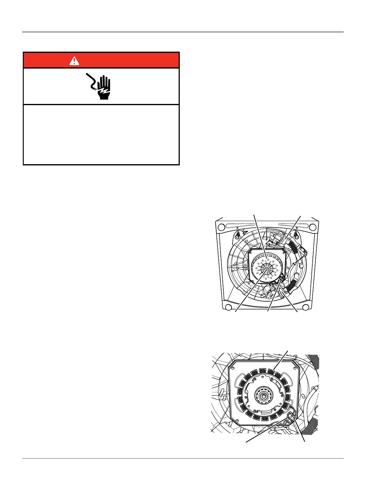
9. Tilt washer back and remove sound pad (if equipped) to
access the drive system (see Figure 1).
3$*(
FOR SERVICE TECHNICIAN’S USE ONLY
DO NOT REMOVE OR DESTROY
¾ If 120VAC is present, go to step 8.
¾ If 120VAC is not present, go to step 12.
8. Unplug washer or disconnect power.
9. Tilt washer back and remove sound pad
(if equipped) to access the drive system (see
Figure 3a).
10. Visually check the electrical connections
to the shifter.
¾ If visual check passes, go to step 11.
¾ If connections are loose, reconnect the
electrical connections and repeat step 1.
11. With an ohmmeter, check the harness for
continuity between the shifter and main control
using the following pinouts. See chart below.
¾ If there is continuity, go to step 12.
¾ If there is no continuity, replace the lower
washer harness and repeat step 1.
12. Remove the motor bolt, then the motor
cover (see Figure 3b). Remove the motor stator
and the shifter coil and confirm that the slider
on the motor shaft moves freely (see Figure 4).
¾ If slider moves freely, and there are no
indications of rubbing on the inside diameter
of the shifter coil and outside diameter of the
slider, go to step 13.
¾ If slider binds or does not move freely, or
there are indications of rubbing on the inside
diameter of the shifter coil or outside diameter
of the slider, replace the drive.
a. Unplug washer or disconnect power.
b. Replace the drive.
c. Reassemble all parts and panels.
d. Plug in washer or reconnect power.
Perform Service Diagnostics to verify repair.
13. If the preceding steps did not correct the
problem, replace the main control.
a. Unplug washer or disconnect power.
b. Replace the main control.
c. Reassemble all parts and panels.
d. Plug in washer or reconnect power.
Perform Service Diagnostics to verify repair.
TEST #3b: Drive System – Motor
This test checks the wiring to the motor and
the motor itself.
NOTE: Drain water from tub and remove any
wash load items present in the basket.
1. See Activating Service Diagnostic Mode,
page 2, and check the motor and electrical
connections by performing the Low, Mid, and
High Speed Spin Test under Service Load
Control Mode, page 4. The following steps
assume that this step failed.
2. Unplug washer or disconnect power.
3. Check to see if impeller will turn freely and
is not connected to the basket.
NOTE: Rotating the impeller quickly can cause
the UI to attempt to power up, and may cause
audible feedback and the main control to power
up and apply braking torque to the impeller.
¾ If impeller turns freely, go to step 4.
¾ If impeller does not turn freely, determine
what is causing the mechanical friction or
lockup.
Shifter and Pump Connector Harness
J4-1 (White wire)
J4-7 (Orange wire)
To shifter connector Pin 3 (White wire)
To shifter connector Pin 1 (Orange wire)
Figure 3a - Drive Area, Viewed From Bottom,
Sound Pad (If Equipped) Removed
Figure 3b - Motor Cover Removed
Figure 4 - Checking Slider Movement/Appearance
Motor Cover
Motor Bolt
Recirculation Pump
Drain Pump
Motor/Shifter
Connector
Stator
Motor ConnectionShifter Connection
Figure 1 - Drive Area, Viewed From Bottom,
Sound Pad (if equipped) Removed
3$*(
FOR SERVICE TECHNICIAN’S USE ONLY
DO NOT REMOVE OR DESTROY
¾ If 120VAC is present, go to step 8.
¾ If 120VAC is not present, go to step 12.
8. Unplug washer or disconnect power.
9. Tilt washer back and remove sound pad
(if equipped) to access the drive system (see
Figure 3a).
10. Visually check the electrical connections
to the shifter.
¾ If visual check passes, go to step 11.
¾ If connections are loose, reconnect the
electrical connections and repeat step 1.
11. With an ohmmeter, check the harness for
continuity between the shifter and main control
using the following pinouts. See chart below.
¾ If there is continuity, go to step 12.
¾ If there is no continuity, replace the lower
washer harness and repeat step 1.
12. Remove the motor bolt, then the motor
cover (see Figure 3b). Remove the motor stator
and the shifter coil and confirm that the slider
on the motor shaft moves freely (see Figure 4).
¾ If slider moves freely, and there are no
indications of rubbing on the inside diameter
of the shifter coil and outside diameter of the
slider, go to step 13.
¾ If slider binds or does not move freely, or
there are indications of rubbing on the inside
diameter of the shifter coil or outside diameter
of the slider, replace the drive.
a. Unplug washer or disconnect power.
b. Replace the drive.
c. Reassemble all parts and panels.
d. Plug in washer or reconnect power.
Perform Service Diagnostics to verify repair.
13. If the preceding steps did not correct the
problem, replace the main control.
a. Unplug washer or disconnect power.
b. Replace the main control.
c. Reassemble all parts and panels.
d. Plug in washer or reconnect power.
Perform Service Diagnostics to verify repair.
TEST #3b: Drive System – Motor
This test checks the wiring to the motor and
the motor itself.
NOTE: Drain water from tub and remove any
wash load items present in the basket.
1. See Activating Service Diagnostic Mode,
page 2, and check the motor and electrical
connections by performing the Low, Mid, and
High Speed Spin Test under Service Load
Control Mode, page 4. The following steps
assume that this step failed.
2. Unplug washer or disconnect power.
3. Check to see if impeller will turn freely and
is not connected to the basket.
NOTE: Rotating the impeller quickly can cause
the UI to attempt to power up, and may cause
audible feedback and the main control to power
up and apply braking torque to the impeller.
¾ If impeller turns freely, go to step 4.
¾ If impeller does not turn freely, determine
what is causing the mechanical friction or
lockup.
Shifter and Pump Connector Harness
J4-1 (White wire)
J4-7 (Orange wire)
To shifter connector Pin 3 (White wire)
To shifter connector Pin 1 (Orange wire)
Figure 3a - Drive Area, Viewed From Bottom,
Sound Pad (If Equipped) Removed
Figure 3b - Motor Cover Removed
Figure 4 - Checking Slider Movement/Appearance
Motor Cover
Motor Bolt
Recirculation Pump
Drain Pump
Motor/Shifter
Connector
Stator
Motor ConnectionShifter Connection
Figure 2 - Motor Cover (Rotor) Removed
Recirculaon Pump
Motor Bolt Motor/Shier
Connector
Motor Cover
Drain Pump
Stator
Shier Connecon Motor Connecon
 Loading...