TESTING
Whirlpool 2014 CABRIO
®
Direct Drive Washer
n
6-15
For Service Technician Use Only
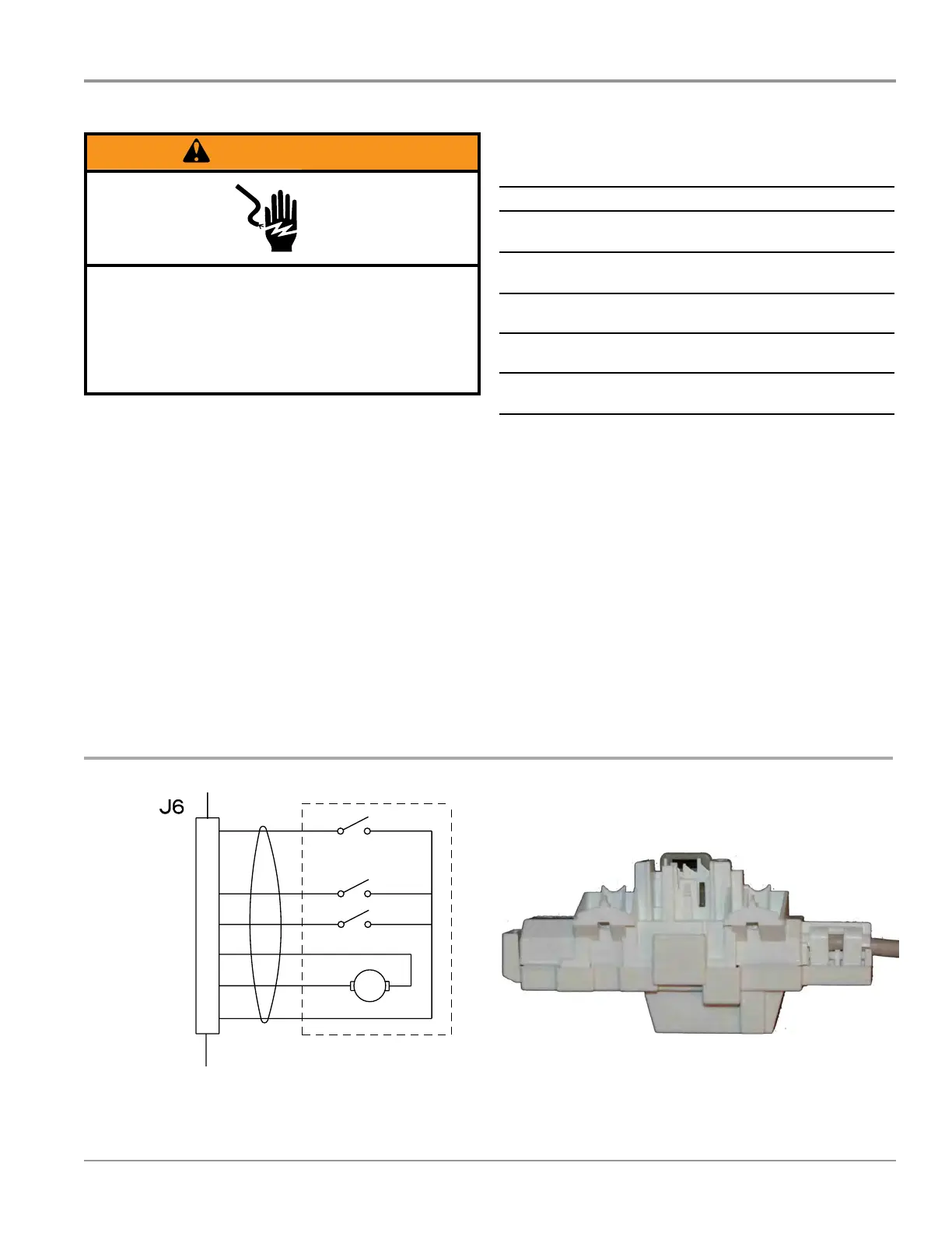
TEST #8: Lid Lock
Perform the following checks if the washer does not lock (or
unlock).
1. Check the lid lock by performing Lid Lock test under
Service Load Control Mode in Service Diagnosc Mode on
page 5-5. The following steps assume that this step was
unsuccessful.
2. Unplug washer or disconnect power.
3. Remove console to access main control.
4. Visually check that the J6 connector is inserted all the way
into the main control.
¾ If visual check passes, go to step 5.
¾ If connector is not inserted properly, reconnect J6 and
repeat step 1.
5. Check the lid lock motor winding and switches by
removing J6 from the main control and checking the
resistance values shown in the following table:
LID LOCK RESISTANCE
Component
Resistance
Unlocked
Resistance
Locked
Contacts
Motor
Winding
35 W
(±5 W)
35 W
(±5 W)
J6-2 J6-3
Lock Switch-
Home
0 W
Open
Circuit
J6-1 J6-4
Lock Switch-
Lock
Open
Circuit
0 W J6-1 J6-7
Lock Switch-
Lid
Lid Closed = 0 W
Lid Open = Open Circuit
J6-1 J6-5
¾ If resistance values are good, go to step 6.
¾ If switch measurements do not match the values
shown in the table for unlocked (or locked) condion,
a problem exists in the lid lock. Replace the lid lock
mechanism.
6. If the preceding steps did not correct the lock problem,
replace the main control.
a. Unplug washer or disconnect power.
b. Replace the main control.
c. Reassemble all parts and panels.
d. Plug in washer or reconnect power. Perform Service
Diagnoscs to verify repair.
3$*(
FOR SERVICE TECHNICIAN’S USE ONLY
DO NOT REMOVE OR DESTROY
Wiring Diagram
IMPORTANT: Electrostatic discharge may cause damage to machine control electronics. See page 1 for
ESD information.
NOTE: Schematic shows lock switch open.
Figure 8 - Wiring Diagram
RECIRC.
PUMP
DRAIN
PUMP
NOT ON ALL MODELS
120 VAC PUMPS
& SHIFTER
SHIFTER
COIL
W
OR
W
LBU W
7 5 3 1
4 3 1 6
3 PHASE
BPM MOTOR
4 3 2 1
BK BR R
VS3
VS1
VS2
BPM MOTOR
DRIVE
NOT ON ALL MODELS
HEATER
ELEMENT
1 2
BK GY
1
2
3
BK
G
W
G
L1
G
N
120 VAC
POWER
CORD
AA BB
MOTOR
PLATE
CABINET
G/Y
RTN (VSS)
VALVE
THERMISTOR
SOFTENER
BLEACH/OXI
MAIN HOT
MAIN COLD
THERMISTOR
BK
BK
T
W
OR
V
R
BU
1
2
3
4
5
6
7
8
9
10
11
12
WATER INLET VALVE
120 VAC
GROUND CIRCUIT
5V
WIDE
RTN (VSS)
1 2 3
SMART UI
SPEAKER
BK BU Y
LOCK SW
LID SW
HOME SW
LOCK MOTOR
LOCK MOTOR
SW OUT
1
2
3
4
5
6
7
W
R
BK
BU
BR
G
GRAY
JACKET
DC LOCK
LOCK
LID
HOME
12 VDC MOTOR
1
3
1
3
1
3
1
3
1 3
BU
(NOT ON
ALL MODELS)
FULL WAVE
BRIDGE
RECTIFIER
NEUT
L1 N
L1
G
N
RECIRC.
NEU
DRAIN
PUMP
ON BOARD
PRESSURE
TRANSDUCER
PRESSURE
HOSE TO TUB
SHIFTER
HF RETURN
Figure 1 - Lid Lock Schematic Figure 2 - Lid Lock
WARNING
Electrical Shock Hazard
Disconnect power before servicing.
Failure to do so can result in death or
electrical shock.
Replace all parts and panels before operating.
 Loading...