EasyManuals Logo

Yamaha F75 User Manual

Yamaha F75
234 pages
To Next Page IconTo Next Page
To Previous Page IconTo Previous Page
Page #145 background imageLoading...
Page #145 background image
FMU2579Z
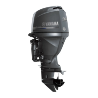
Diagramme des composants
REMARQUE:
* Peuvent ne pas être exactement comme illustré ; peuvent également ne pas être inclus
dans l’équipement standard de tous les modèles (commande du revendeur).
ZMU08196
TRIP TIME BATT
Km/h
knot
mph
km
mile
SPEED
YAMAHA
set
mode
11 12
14
13
15
16
1. Capot supérieur
2. Levier(s) de verrouillage du capot
3. Plaque anticavitation
4. Dérive (anode)
5. Hélice*
6. Entrée d’eau de refroidissement
7. Support de presse
8. Dispositif de rinçage
9. Séparateur d’eau
10.Interrupteur de trim
11.Boîtier de commande à distance (type à mon-
tage latéral)*
12.Indicateur de vitesse numérique*
13.Compte-tours numérique*
14.Réservoir de carburant*
15.Réservoir de carburant*
16.Barre franche*
Composants
25
©2019 Yamaha Motor Corporation, U.S.A.

Table of Contents

Other manuals for Yamaha F75

Questions and Answers:

Question and Answer IconNeed help?

Do you have a question about the Yamaha F75 and is the answer not in the manual?

Yamaha F75 Specifications

General IconGeneral
Cylinders4
Fuel Induction SystemEFI (Electronic Fuel Injection)
Prop Shaft Horsepower75 hp
Full Throttle RPM Range5000-6000 RPM
Gear Ratio2.15:1
Starting SystemElectric
Engine Type4-stroke
Alternator Output25A
Steering Angle35° from center, either direction
Shaft Length20 in., 25 in.
Fuel Tank CapacityN/A (External)
Recommended FuelRegular Unleaded (Minimum Pump Octane 87)
Warranty3-Year Limited Warranty

Related product manuals