Components
25
mercial users should conform to relevant
licensing or approval authority regula-
tions.
Fuel joint
This joint is used to connect the fuel line.
Fuel tank cap
This cap seals the fuel tank. When removed,
the tank can be filled with fuel. To remove the
cap, turn it counterclockwise.
Air vent screw
This screw is on the fuel tank cap. To loosen
the screw, turn it counterclockwise.
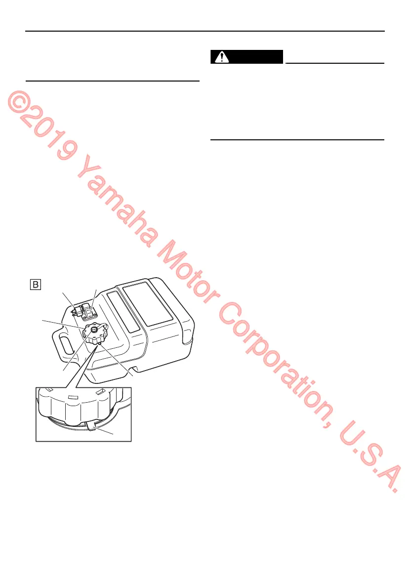
If using the type “B” portable fuel tank, the
parts of the fuel tank are as follows.
This fuel tank conforms to Evaporative Emis-
sions Regulations for marine fuel systems en-
acted by the US Environmental Protection
Agency (EPA).
EWM00021
The fuel tank supplied with this engine is
its dedicated fuel reservoir and must not
be used as a fuel storage container. Com-
mercial users should conform to relevant
licensing or approval authority regula-
tions.
Fuel joint
This joint is used to connect the fuel line.
Fuel gauge
This gauge shows the approximate amount
of fuel remaining in the fuel tank.
Pressure relief tab
This tab is attached to the filler hole of the fuel
tank.
Fuel tank cap
This cap seals the fuel tank. To loosen the
cap, press and hold the pressure relief tab
and turn the cap counterclockwise.
Air vent screw
This screw is on the fuel tank cap. When turn-
ing the air vent screw counterclockwise, it is
loosened and the pressure in the fuel tank is
released to a certain pressure. Air is allowed
to enter the fuel tank while operating the en-
gine.
EMU26182
Remote control box
The remote control lever actuates both the
shifter and the throttle. The electrical switch-
es are mounted on the remote control box.
1. Fuel joint
2. Fuel gauge
3. Pressure relief tab
4. Fuel tank cap
5. Air vent screw
U6D63EE0.book Page 25 Friday, December 12, 2014 9:39 AM
©2019 Yamaha Motor Corporation, U.S.A.

 Loading...