EasyManuals Logo

Yamaha F75 User Manual

Yamaha F75
234 pages
To Next Page IconTo Next Page
To Previous Page IconTo Previous Page
Page #29 background imageLoading...
Page #29 background image
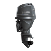
Components
23
EMU2579Z
Components diagram
TIP:
* May not be exactly as shown; also may not be included as standard equipment on all models
(order from dealer).
ZMU08196
TRIP TIME BATT
Km/h
knot
mph
km
mile
SPEED
YAMAHA
set
mode
11 12
14
13
15
16
1. Top cowling
2. Cowling lock lever(s)
3. Anti-cavitation plate
4. Trim tab (anode)
5. Propeller*
6. Cooling water inlet
7. Clamp bracket
8. Flushing device
9. Water separator
10.Power trim and tilt switch
11.Remote control box (side mount type)*
12.Digital speedometer*
13.Digital tachometer*
14.Fuel tank*
15.Fuel tank*
16.Tiller handle*
U6D63EE0.book Page 23 Friday, December 12, 2014 9:39 AM
©2019 Yamaha Motor Corporation, U.S.A.

Table of Contents

Other manuals for Yamaha F75

Questions and Answers:

Question and Answer IconNeed help?

Do you have a question about the Yamaha F75 and is the answer not in the manual?

Yamaha F75 Specifications

General IconGeneral
Cylinders4
Fuel Induction SystemEFI (Electronic Fuel Injection)
Prop Shaft Horsepower75 hp
Full Throttle RPM Range5000-6000 RPM
Gear Ratio2.15:1
Starting SystemElectric
Engine Type4-stroke
Alternator Output25A
Steering Angle35° from center, either direction
Shaft Length20 in., 25 in.
Fuel Tank CapacityN/A (External)
Recommended FuelRegular Unleaded (Minimum Pump Octane 87)
Warranty3-Year Limited Warranty

Related product manuals