EasyManuals Logo

Yamaha XT660X Service Manual

Yamaha XT660X
462 pages
To Next Page IconTo Next Page
To Previous Page IconTo Previous Page
Page #422 background imageLoading...
Page #422 background image
8 - 40
+
ELEC
SIGNALING SYSTEM
EAS00796
CHECKING THE SIGNALING SYSTEM
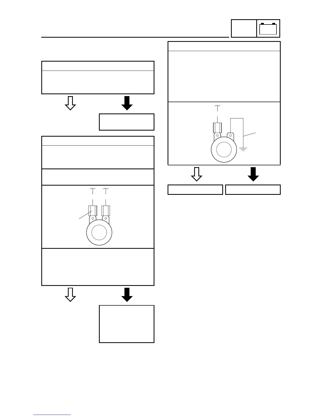
1. The horn fails to sound.
YES
NO
YES
NO
YES
NO
1. Horn switch
Check the horn switch for continuity.
Refer to CHECKING THE SWITCHES.
Is the horn switch OK?
Replace the left han-
dlebar switch.
2. Voltage
Connect the pocket tester (DC 20 V) to the
horn connector at the horn terminal as
shown.
Positive tester probe
pink
1
Negative tester probe
ground
Set the main switch to ON.
Push the horn switch.
Measure the voltage (DC 12 V) of pink at
the horn terminal.
Is the voltage within specification?
The wiring circuit
from the main switch
to the horn connector
is faulty and must be
repaired.
P B
1
3. Horn
Disconnect the black connector at the horn
terminal.
Connect a jumper lead
1
to the horn ter-
minal and ground the jumper lead.
Set the main switch to ON.
Push the horn switch.
Does the horn sound?
The horn is OK. Replace the horn.
P
1

Table of Contents

Other manuals for Yamaha XT660X

Questions and Answers:

Question and Answer IconNeed help?

Do you have a question about the Yamaha XT660X and is the answer not in the manual?

Yamaha XT660X Specifications

General IconGeneral
Displacement660cc
Bore x Stroke100.0 mm x 84.0 mm
Compression Ratio10.0:1
Fuel SystemFuel Injection
Ignition SystemTCI
Transmission5-speed
Final DriveChain
Rear BrakeSingle disc, Ø 245 mm
Front Tyre120/70 R17
Rear Tyre160/60 R17
Maximum Power48 HP (35.3 kW) @ 6, 000 rpm
Maximum Torque58.4Nm (43.1lb-ft) @ 5, 250rpm
Front SuspensionTelescopic fork
Rear SuspensionSwingarm, (link suspension)
Fuel Tank Capacity15 litres
Engine TypeLiquid-cooled, 4-stroke, single cylinder, SOHC, 4-valves

Related product manuals