User Constant Tables
5-83
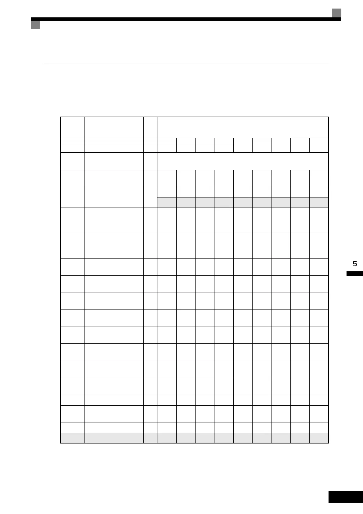
Factory Settings that Change with the Inverter Capacity (o2-04)
The factory settings of the following user constants will change if the Inverter capacity (o2-04) is changed.
200 V Class Inverters
Con-
stant
Number
Name Unit Factory Setting
- Inverter Capacity kW 0.4 0.75 1.5 2.2 3.7 5.5 7.5 11 15
o2-04 kVA selection -012345678
b8-03
Energy-saving filter time
constant
s 0.50 (Open loop vector control)
b8-04
Energy-saving coeffi-
cient
-
288.20 223.70 169.40 156.80 122.90 94.75 72.69 70.44 63.13
C6-01 CT/VT selection -
111111111
0 0 0 0 0 0 0 0 0
C6-02
Carrier frequency selec-
tion (when VT is
selected)
*1 *4
-
6
*2
6
*2
6
*2
6
*2
6
*2
6
*2
6
*2
6
*2
6
*2
-
Carrier frequency selec-
tion upper limit (when
VT is selected)
*1
-666666666
E2-01
(E4-01)
Motor rated current A 1.90 3.30 6.20 8.50 14.00 19.60 26.60 39.7 53.0
E2-02
(E4-02)
Motor rated slip Hz 2.90 2.50 2.60 2.90 2.73 1.50 1.30 1.70 1.60
E2-03
(E4-03)
Motor no-load current A 1.20 1.80 2.80 3.00 4.50 5.10 8.00 11.2 15.2
E2-05
(E4-05)
Motor line-to-line resis-
tance
Ω
9.842 5.156 1.997 1.601 0.771 0.399 0.288 0.230 0.138
E2-06
(E4-06)
Motor leak inductance % 18.2 13.8 18.5 18.4 19.6 18.2 15.5 19.5 17.2
E2-10
Motor iron loss for
torque compensation
W 14 26 53 77 112 172 262 245 272
L2-02
Momentary power loss
ridethru time
s 0.1 0.1 0.2 0.3 0.5 1.0 1.0 1.0 2.0
L2-03
Min. baseblock (BB)
time
s 0.1 0.2 0.3 0.4 0.5 0.6 0.7 0.8 0.9
L2-04 Voltage recovery time s 0.3 0.3 0.3 0.3 0.3 0.3 0.3 0.3 0.3
L2-08
Frequency reduction
gain at KEB start
°C959595959595959595
L8-02 Overheat pre-alarm level °C 95 95 95 100 95 95 95 95 90
N5-02 Motor acceleration time s 0.178 0.142 0.166 0.145 0.154 0.168 0.175 0.265 0.244
 Loading...