Connection Diagram
2-3
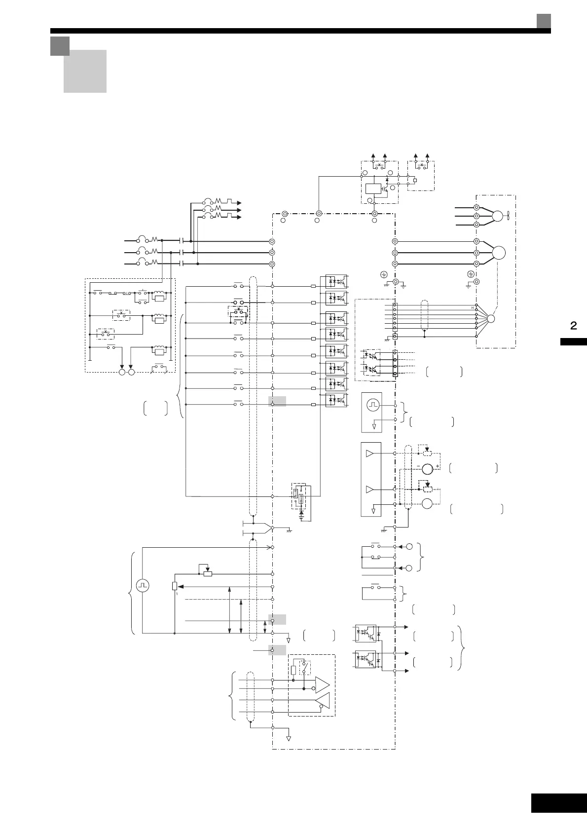
Connection Diagram
The connection diagram of the Inverter is shown in Fig 2.2.
When using the Digital Operator, the motor can be operated by wiring only the main circuits.
Fig 2.2 Connection Diagram (Model CIMR-F7A2022 Shown Above)
Inverter
CIMR-F7A2022
P2
PC
Open collector 1
Open collector 2
Multi-function
open-collector outputs
48 VDC 50 mA max.
P1
Default: Frequency
agree signal
Default: Zero-
speed
MA
MC
MB
Error contact output
250 VAC, 10 mA min. 1 A max.
30 VAC, 10 mA min. 1 A max.
M1
M2
Multi-function contact oputput
250 VAC, 10 mA min. 1 A max.
30 VAC, 10 mA min. 1 A max.
Default: Running
signal
AC
MP
Pulse train output
Default: Output
frequency
3-phase power
2
to 24
V
50/60 Hz
R/L1
S/L2
T/L3
1MCCB
T
S
R
S5
S8
(Main speed switching)
External
baseblock command
S1
S2
S3
S4
Forward Run/Stop
Reverse Run/Stop
External fault
Fault reset
Multi-step speed reference 1
contact inputs
Multi-function
Factory
settings
IG
MEMOBUS
communications
RS-485/422
R+
R-
S-
S+
Braking Unit
(optional)
FM
AM
Multi-function analog output 1
AC
FM
E(G)
-10 to 10 V 2 mA
Default: Output frequency
0 to +10 V
Default: Output current
0 to +10 V
-10 to 10 V 2 mA
Multi-function analog output 2
Ammeter adjustment
20 kΩ
SC
E (G)
Shield wire
connection terminal
S6
S7
Multi-step speed
reference 2
Jog frequency
selection
CN5 (NPN setting)
+24V 8mA
+24V
P
4 to 20 mA
0 to 10 V
0 to 10 V
Pulse train input
RP
+V
A2
A3
AC
0V
Master speed
pulse train
Frequency setting power
Master speed reference
Multi-function anlog input
Master speed reference
4 to 20 mA (250
Ω)
[0 to 10 V (20 k
Ω
) input]
+15 V, 20 mA
0 to 10 V (20 kΩ)
0 to 10 V (20 kΩ)
Frequency
Frequency setting
adjustment
setter
External
frequency
references
-V
(15V 20mA)
Terminating
resistance
Factory setting:
Not used
PG
PG-B2
TA1
1
2
3
4
5
6
(optional)
TA3
TA2
1
Pulse monitor output
30 mA max.
Wiring distance:d:
30 m max.
Shieded twisted-pair
wires
G
F
D
U
U/T1
V/T2
W/T3
IM
(Ground to 100 max.)
V
IM
FU
FV
FW
FU
FV
FW
2MCCB
MC
Cooling fan
Motor
A
2MCCB THRX OFF
ON
MC
MC
SA
21
21
A
TRX
TRX
MC
MC
Fault contact
MA
Thermal relay
trip contact
for motor cooling fan
MA
MC
for Braking Unit
-
Level
detector
-
-
+
0
0
B
P
Braking Resistor Unit
(optional)
43 21
+
Thermal switch contact
Thermal relay trip contact
for Braking Resistor Unit
0 to 32 kHz (3 kΩ)
High level: 3.5 to 13.2 V input
0 to 32 kHz (2.2 kΩ)
2k
Ω
2k
Ω
Thermal relay trip contact
Thermal switch contact
A1
Pulse A
Pulse B
1
2
3
34
4
Ammeter adjustment
20 kΩ
AM
 Loading...