10-30
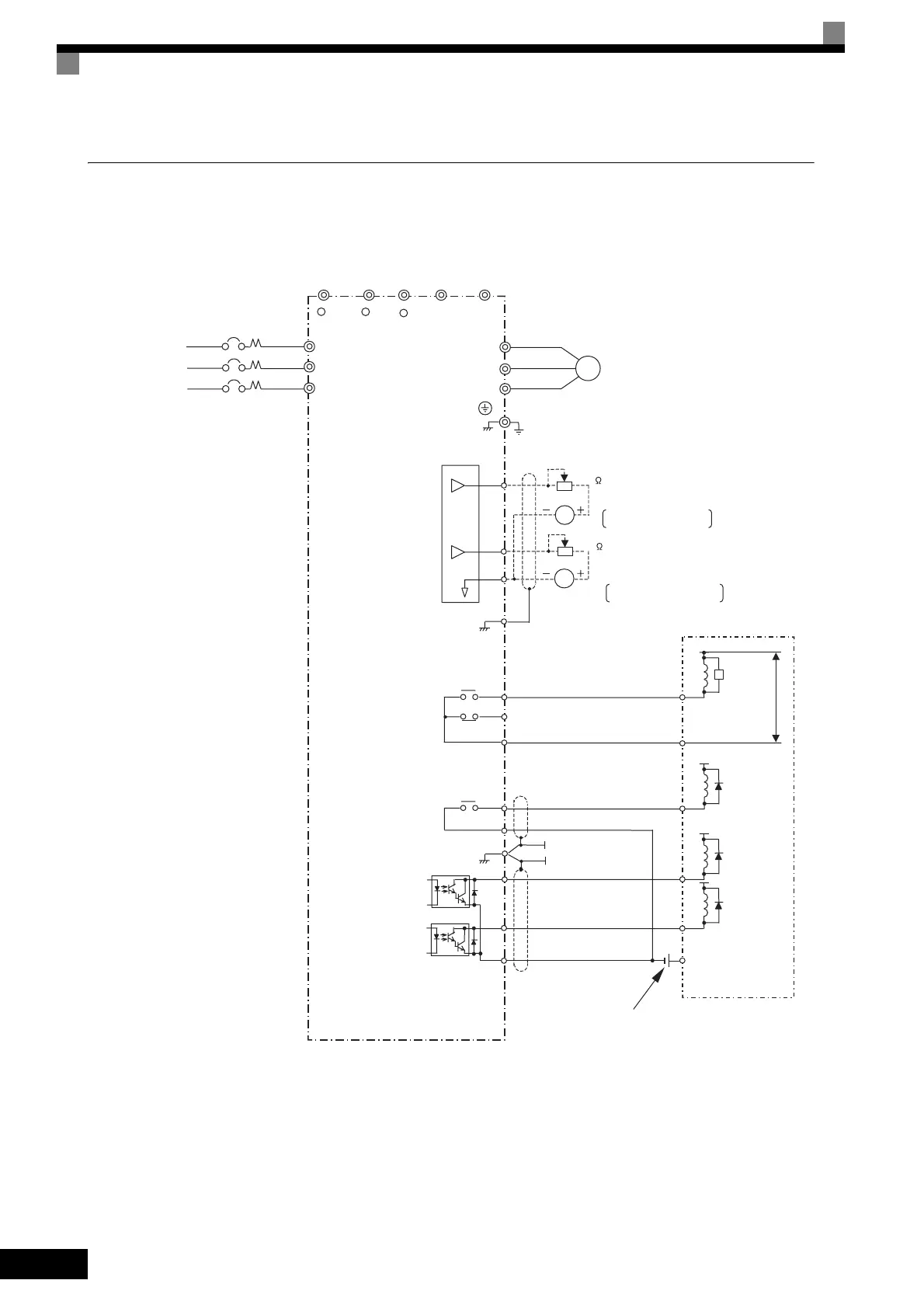
Using Contact and Open Collector Outputs
This example shows wiring for contact outputs and open collector outputs.
The following example is for the CIMR-F7A27P5 (200 V Class Inverter for 7.5 kW).
Fig 10.17
Inverter
U/T1
V/T2
W/T3
IM
Ground
MA
MB
MC
Error contact output
P2
PC
Open collector 1
Multi-function
open collector output
48 VDC 50 mA max.
P1
(Default: zero speed)
M1
M2
Multi-function contact output
(Default: RUN)
T/L3
S/L2
R/L1
3-phase power
M
B
T
S
R
FM
M
Multi-function analog output 1
C
E
G
-10 to +10 V 2 mA
M
FM
Default: Output frequency,
0 to +10 V
Default: Ouput current,
0 to +10 V
-10 to +10 V 2 mA
Multi-function analog output 2
Frequency meter scale adjustment resistor
20 k
B2B1
Ammeter scale adjustment resistor
20 k
Motor
Sequence external power
supply
Surge
absorber
250 VAC max.
30 VDC max.
Flywheel
diode
48 VDC max.
48 VDC max.
Sequence
(Default: Freq agree)
250 VAC, 10 mA min. 1 A max.
30 VDC, 10 mA min. 1 A max.
250 VAC, 10 mA min. 1 A max.
30 VDC, 10 mA min. 1 A max.
E
G
+ 1 + 2
-
Flywheel
diode
Flywheel
diode
Open collector 2
 Loading...