Individual Functions
6-137
Speed Control (ASR) Gain Adjustment for Flux Vector Control (SPEC: E or Later Only)
Use the following procedure to adjust C5-01 and C5-03 with the mechanical system and actual load con-
nected.
Fine Adjustments
When you want even finer gain adjustment, adjust the gain while observing the speed waveform. Constant set-
tings like those shown in the following table will be necessary to monitor the speed waveform.
The multi-function analog outputs have the following functions with these constant settings.
• Multi-function analog output 1 (terminal FM): Outputs Inverter's output frequency (0 to ±10 V).
• Multi-function analog output 2 (terminal AM): Outputs actual motor speed (0 to ±10 V).
Terminal AC is the multi-function analog output common.
We recommend monitoring both the output frequency and the motor speed to monitor the response delay or
deviations from the reference value, as shown in the following diagram.
Constant
No.
Name Setting Explanation
H4-01 Multi-function analog output 1 terminal FM monitor selection 2
Settings that allow multi-func-
tion analog output 1 to be used
to monitor the output frequency.
H4-02 Multi-function analog output 1 terminal FM output gain 1.00
H4-03 Multi-function analog output 1 terminal FM bias 0.0
H4-04 Multi-function analog output 2 terminal AM monitor selection 5
Settings that allow multi-func-
tion analog output 2 to be used
to monitor the motor speed.
H4-05 Multi-function analog output 2 terminal AM output gain 1.00
H4-06 Multi-function analog output 2 terminal AM bias selection 0.00
H4-07 Multi-function analog output 1 terminal signal level selection 1
Settings that allow a 0 to ±10 V
signal range to be monitored.
H4-08 Multi-function analog output 2 terminal signal level selection 1
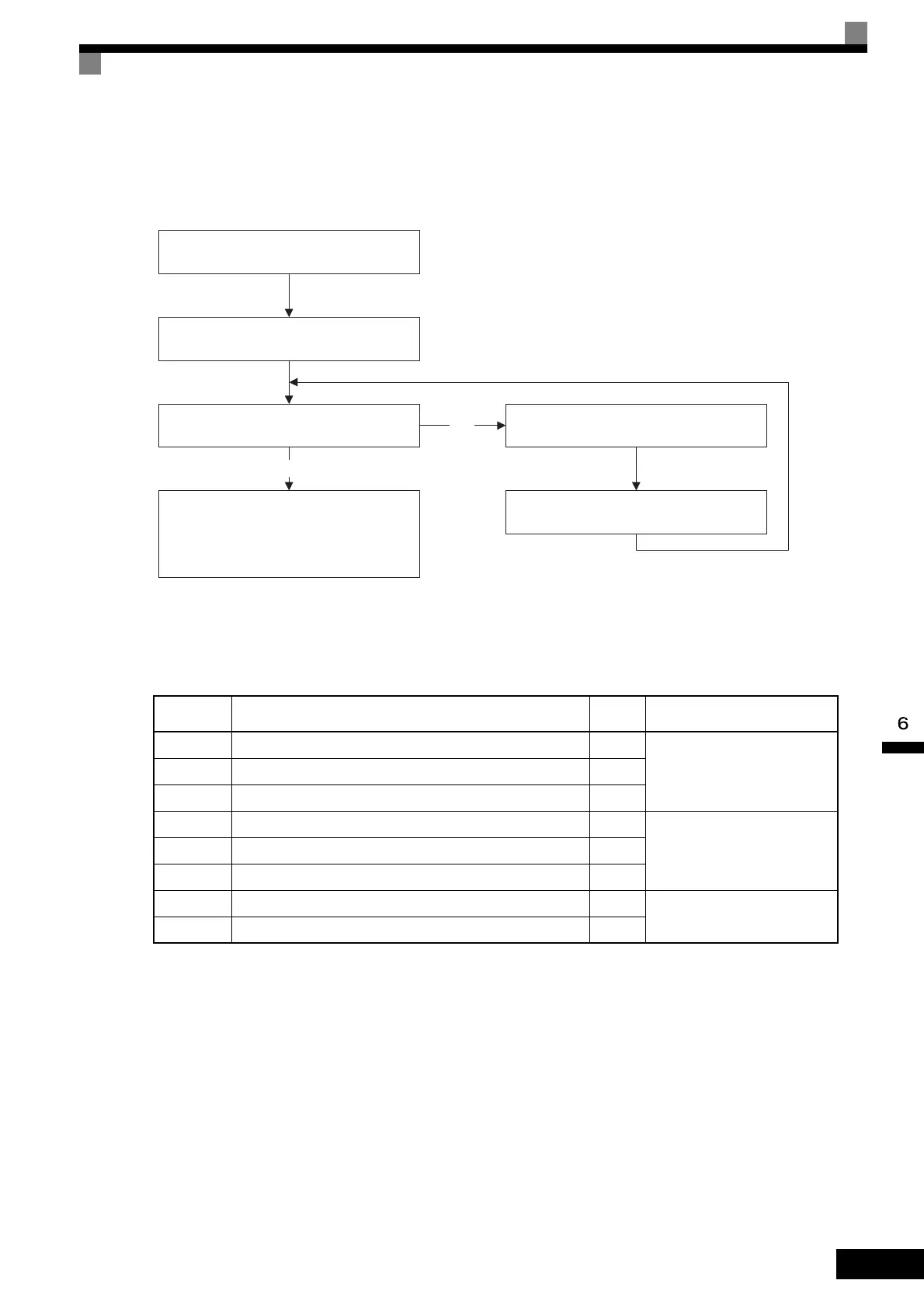
At zero-speed, increase C5-01
(ASR P Gain 1) until there is no oscillation.
At zero-speed, decrease C5-02
(ASR I Time 1) until there is no oscillation.
Does oscillation develop when the motor
operates at the maximum normal operating
speed?
Decrease C5-01 (ASR P Gain 1).
Increase C5-02 (ASR I Time 1).
YES
NO
Adjustment completed.
(When there is higher-level position control,
adjust the position loop gain so that
overshooting/undershooting doesn't occur.)
 Loading...