2-12
Main Circuit Terminal Functions
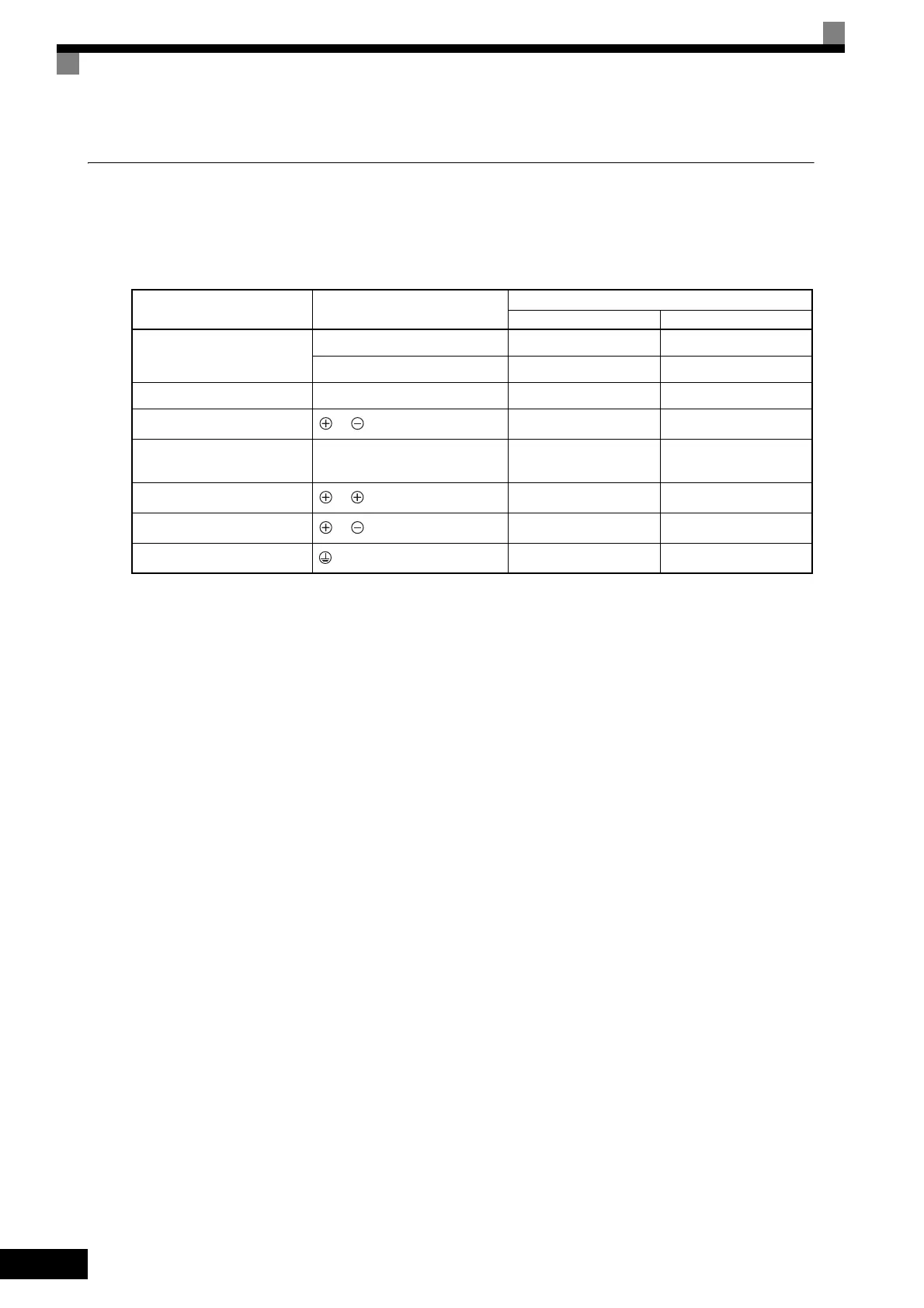
Main circuit terminal functions are summarized according to terminal symbols in Table 2.4. Wire the terminals
correctly for the desired purposes.
Table 2.4 Main Circuit Terminal Functions (200 V Class and 400 V Class)
Purpose Terminal Symbol
Model: CIMR-F7A □
200 V Class 400 V Class
Main circuit power input
R/L1, S/L2, T/L3 20P4 to 2110 40P4 to 4300
R1/L11, S1/L21, T1/L31 2022 to 2110 4022 to 4300
Inverter outputs U/T1, V/T2, W/T3 20P4 to 2110 40P4 to 4300
DC power input
1,
20P4 to 2110 40P4 to 4300
Braking Resistor Unit connec-
tion
B1, B2 20P4 to 2018 40P4 to 4018
DC reactor connection
1, 2
20P4 to 2018 40P4 to 4018
Braking Unit connection
3,
2022 to 2110 4022 to 4300
Ground 20P4 to 2110 40P4 to 4300
 Loading...