6-168
Using Inverters for Elevating Machines
This section describes precautions to be observed when using the Varispeed F7 for elevating machines
such as elevators and cranes.
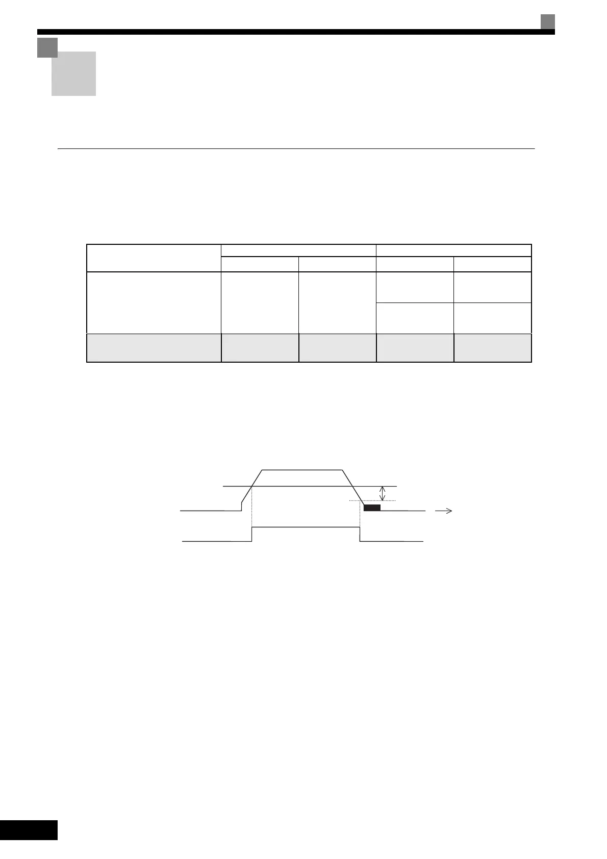
Brake ON/OFF Sequence
Brake ON/OFF Sequence
For the holding brake’s ON/OFF sequence, use the following Inverter output signals according to the set con-
trol method.
* 1. This example shows multi-function output terminals M1-M2 used for the holding brake ON/OFF signal.
Do not set H2-01 to 0 (During run).
* 2. This is the standard setting range for open-loop vector control. For V/f control, set to approximately the motor rated slip frequency +0.5 Hz.
If the set value is too low, the motor torque is insufficient and the load may slip when the brake is applied. Be sure to set L4-01 to a value larger than that
of E1-09 (Min. output frequency) and larger than that of L4-02 shown in Figure 6.80. If the set value is too large, the motor may not run smoothly when
it starts running.
* 3. The hysteresis in frequency detection 2 can be adjusted (from 0.1 to 0.5 Hz) by L4-02 (speed agree detection width). Change the setting to approxi-
mately 0.1 Hz if there are drops while stopping.
Fig 6.80
Control Method
Brake ON/OFF Signal Brake ON/OFF Level Adjustment
Signal Name
Constant
*1
Signal Name
Constant
V/f (A1-02 = 0,
factory setting)
V/f with PG (A1-02 = 1)
Open-loop vector (A1-02 = 2)
Frequency detec-
tion 2
H2-01 = 05
Speed agree detec-
tion level
L4-01 = 1.0 to
3.0 Hz
*2
Speed agree detec-
tion width
L4-02 = 0.1 to
0.5 Hz
*3
Flux vector (A1-02 = 3) During run 2 H2-01 = 37
Zero-speed level
(OFF timing only)
b2-01 = 0.1 to
0.5 Hz
L4-02
L4-01
OFF
ON
Frequency detection 2
Output frequency
Time
 Loading...