Wiring Main Circuit Terminals
2-15
Wiring the Main Circuits
This section describes wiring connections for the main circuit inputs and outputs.
Wiring Main Circuit Inputs
Observe the following precautions for wiring the main circuit power supply inputs.
Installing a Molded-case Circuit Breaker
Always connect the power input terminals (R, S, and T) and power supply via a molded-case circuit breaker
(MCCB) suitable for the Inverter.
• Choose an MCCB with a capacity of 1.5 to 2 times the Inverter's rated current.
• For the MCCB's time characteristics, be sure to consider the Inverter's overload protection (one minute at
150% of the rated output current).
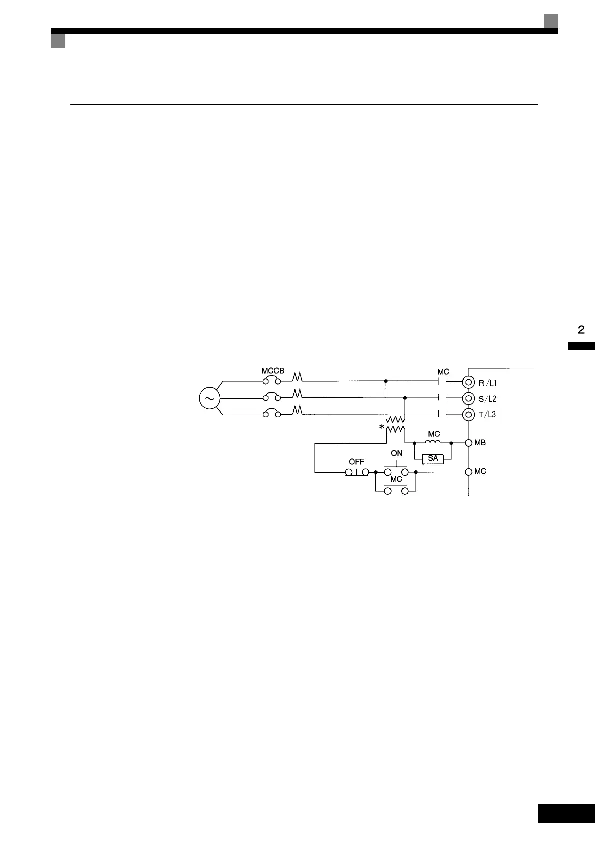
• If the same MCCB is to be used for more than one Inverter, or other devices, set up a sequence so that the
power supply will be turned OFF by a fault output, as shown in Fig 2.6.
Fig 2.6 MCCB Installation
Installing a Ground Fault Interrupter
Inverter outputs use high-speed switching, so high-frequency leakage current is generated. Therefore, at the
Inverter primary side, use a ground fault interrupter to detect only the leakage current in the frequency range
that is hazardous to humans and exclude high-frequency leakage current.
• For the special-purpose ground fault interrupter for Inverters, choose a ground fault interrupter with a sen-
sitivity amperage of at least 30 mA per Inverter.
• When using a general ground fault interrupter, choose a ground fault interrupter with a sensitivity amper-
age of 200 mA or more per Inverter and with an operating time of 0.1 s or more.
* For 400 V Class Inverters, connect a 400/200 V transformer.
20P4 to 2030: 3-phase,
200 to 240 VAC, 50/60 Hz
2037 to 2110: 3-phase,
200 to 230 VAC, 50/60 Hz
40P4 to 4300: 3-phase,
380 to 460 VAC, 50/60 Hz
Power
supply
Inverter
Fault output
(NC)
 Loading...