Input Terminal Functions
6-81
Application Precautions
• When d4-01 is set to 1, the output frequency on hold is stored even after the power supply is turned OFF. If
performing operations using this frequency after the Inverter has also been turned OFF, input the Run
Command with the Acceleration/Deceleration Ramp Hold turned ON.
• When d4-01 is set to 0 and a Run Command is input while the Acceleration/Deceleration Ramp Hold is
turned ON, the output frequency will be set to zero.
• If you input an Acceleration/Deceleration Ramp Hold command by error when decelerating during posi-
tioning, deceleration may be canceled.
Raising and Lowering Frequency References Using Contact Signals (UP/
DOWN)
The UP and DOWN commands raise and lower Inverter frequency references by turning ON and OFF a multi-
function contact input terminal S3 to S8.
To use this function, set one of the constants H1-01 to H1-06 (multi-function contact input terminal S3 to S8
function selection) to 10 (UP command) and 11 (DOWN command). Be sure to allocate two terminals so that
the UP and DOWN commands can be used as a pair.
The output frequency depends on the acceleration and deceleration time. Be sure to set b1-02 (Run Command
selection) to 1 (Control circuit terminal).
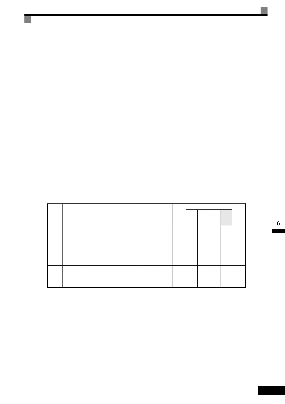
Related Constants
Precautions
When setting and using UP and DOWN commands, observe the following precautions.
Setting Precautions
If multi-function input terminals S3 to S8 are set as follows, operation error OPE03 (Invalid multi-function
input selection) will occur:
• Only either the UP command or DOWN command has been set.
• UP/DOWN commands and Acceleration/Deceleration Ramp Hold have been allocated at the same time.
Con-
stant
Number
Name Description
Setting
Range
Factory
Setting
Change
during
Opera-
tion
Control Methods
MEMO
BUS
Regis-
ter
V/f
V/f
with
PG
Open
Loop
Vec-
tor
Flux
Vec-
tor
d2-01
Frequency
reference
upper limit
Set the output frequency upper
limit as a percent, taking the
max. output frequency to be
100%.
0.0 to
110.0
100.0% No A A A A 289H
d2-02
Frequency
reference
lower limit
Sets the output frequency lower
limit as a percentage of the max-
imum output frequency.
0.0 to
110.0
0.0% No A A A A 28AH
d2-03
Master speed
reference
lower limit
Set the master speed reference
lower limit as a percent, taking
the max. output frequency to be
100%.
0.0 to
110.0
0.0% No A A A A 293H
 Loading...