Terminal Block Configuration
2-5
Terminal Block Configuration
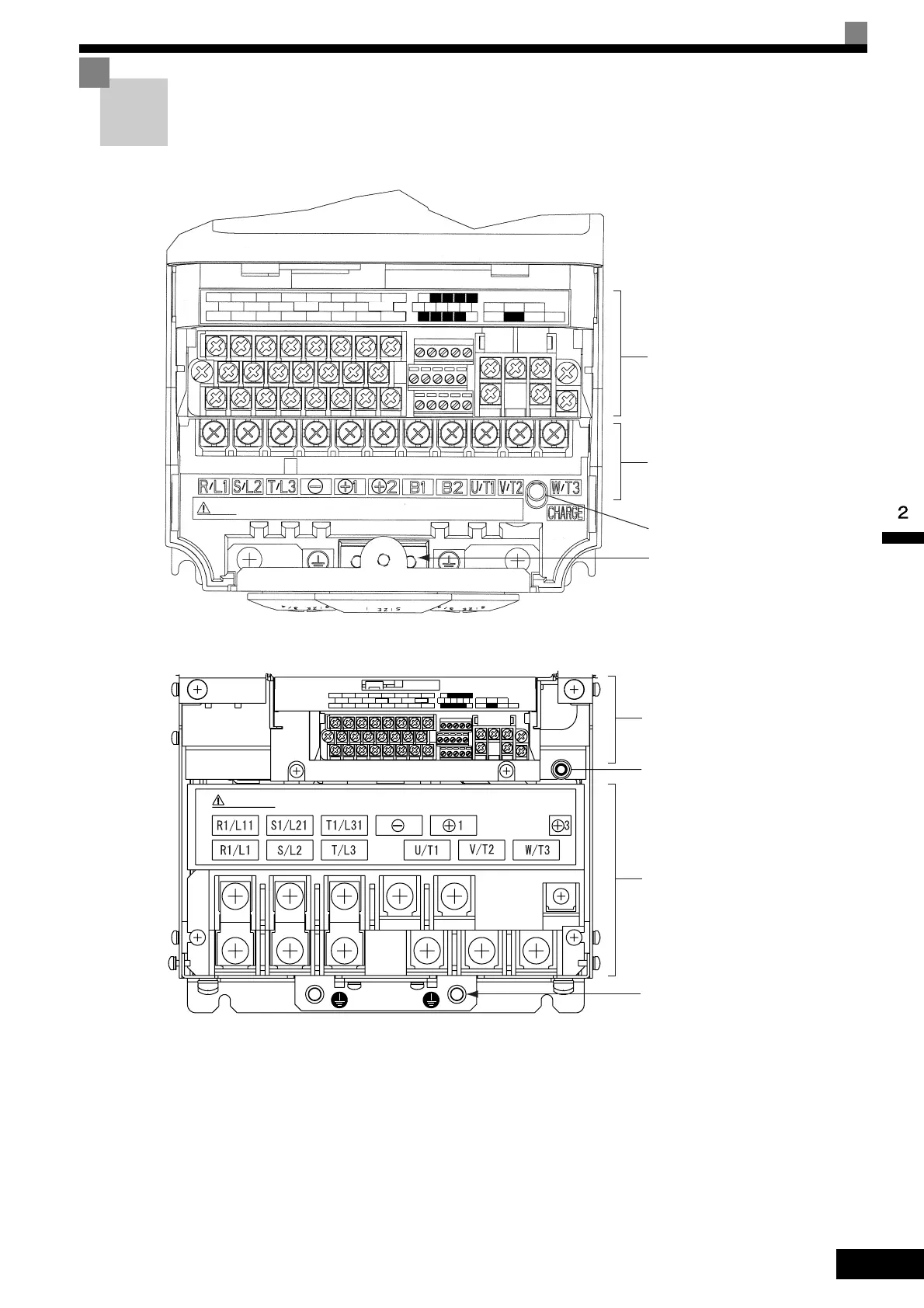
The terminal arrangement for 200 V Class Inverters are shown in Fig 2.3 and Fig 2.4.
Fig 2.3 Terminal Arrangement (200 V Class Inverter with SPEC: E or later for 0.4 kW Shown Above)
Fig 2.4 Terminal Arrangement (200 V Class Inverter with SPEC: E or later for 22 kW Shown Above)
Control circuit terminals
Main circuit terminals
Charge indicator
Ground terminal
E (G) FM AC AM
SC A1 A2 +V AC
P1 P2 PC
S1 S2 S3 S4
S5
S6 S7
SC
MA
M1
MB MC
M2
E (G)
MP
RP R+ R- S+ S-
IG
A3 -V
S8
Control circuit terminals
Charge indicator
Main circuit terminals
Ground terminal
 Loading...