6-88
Output Terminal Functions
The output terminal function, which sets the output methods by switching the settings of H2-01 to H2-03
(Multi-function contact output terminals M1-M2, P1-PC, and P2-PC), is described here.
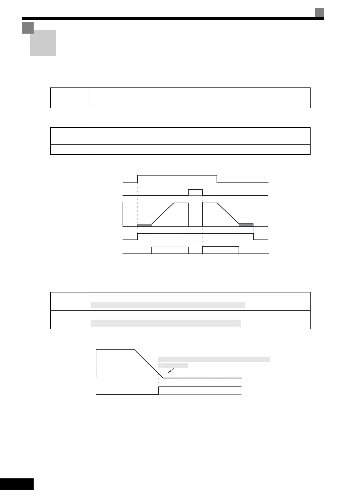
During Run (Setting: 0)
During Run 2 (Setting: 37)
• These outputs can be used to indicate the Inverter's operating status.
Fig 6.54 Timing Chart for “During RUN” Output
Zero-speed (Setting: 1)
Fig 6.55 Timing Chart for Zero-speed
OFF The Run Command is OFF and there is not output voltage.
ON The Run Command is ON or a voltage is being output.
OFF
The Inverter is not outputting a frequency. (Baseblock, DC injection braking, initial excitation, or
stopped)
ON The Inverter is outputting a frequency.
OFF
The output frequency is greater than the minimum output frequency (E1-09).
ON
The output frequency is less than the minimum output frequency (E1-09).
ON
ON
OFF
OFF
ONOFF
ON
Run Command
Baseblock command
Output frequency
During run 1 output
During run 2 output
OFF
[With flux vector control, is greater than the zero-speed level (b2-01).]
[With flux vector control, is less than the zero-speed level (b2-01).]
OFF
Output frequency
Zero-speed output
ON
Minimum output frequency (E1-09)
[Zero-speed level (b2-01) when flux vector control is
being used.]
 Loading...