Installation Orientation and Space
1-11
Installation Orientation and Space
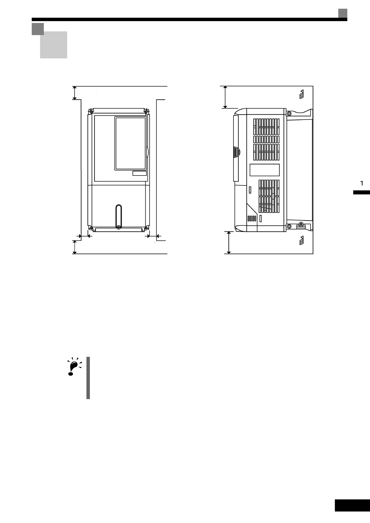
Install the Inverter vertically so as not to reduce the cooling effect. When installing the Inverter, always
provide the following installation space to allow normal heat dissipation.
200 V Class Inverters of 110 kW or 400 V Class Inverters of 160 to 220 kW*: A = 120, B = 120
400 V Class Inverters of 300 kW*: A = 300, B = 300
All other Inverters*: A = 50, B = 120
*If, however, there is a fan in the top of the control panel with sufficient exhaust capacity, the following
dimensions may be used: A = 50, B = 120.
Fig 1.8 Inverter Installation Orientation and Space
IMPORTANT
1. The same space is required horizontally and vertically for both Open Chassis (IP00) and Enclosed Wall-
mounted [IP20, NEMA 1 (Type 1)] Inverters.
2. Always remove the protection covers before installing a 200 or 400 V Class Inverter with an output of 18.5
kW or less in a panel. Refer to Page 1-17 on how to remove the protection covers.
Always provide enough space for suspension eye bolts and the main circuit lines when installing a 200 or
400 V Class Inverter with an output of 22 kW or more in a panel.
A mm min.
50 mm min.
30 mm min.
30 mm min.
B mm min.
120 mm min.
Air
Air
Vertical SpaceHorizontal Space
 Loading...