Monitor Constants
6-93
Using Pulse Train Monitor Contents
This section explains pulse monitor constants.
Related Constants
Selecting Pulse Monitor Items
Output digital operator monitor items (U1- [status monitor]) from pulse monitor terminal MP-AC. Refer
to Chapter 5 User Constants, and set the part of U1- (Status monitor). The possible monitor selec-
tions are limited as follows: U1-01, 02, 05, 20, 24, 36.
Adjusting the Pulse Monitor Items
Adjust the pulse frequency output from pulse monitor terminal MP-SC. Set the pulse frequency output when
100% frequency is output to H6-07.
Set H6-06 to 2, and H6-07 to 0, to output the frequency synchronous with the Inverter's U-phase output.
Application Precautions
When using a pulse monitor constant, connect a peripheral device according to the following load conditions.
If the load conditions are different, there is a risk of characteristic insufficiency or damage to the machinery.
Con-
stant
Number
Name Description
Setting
Range
Factory
Setting
Change
during
Opera-
tion
Control Methods
MEMO
BUS
Regis-
ter
V/f
V/f
with
PG
Open
Loop
Vec-
tor
Flux
Vec-
tor
H6-06
Pulse train
monitor
selection
Select the pulse train monitor
output items (value of the
part of U1-).
There are two types of monitor
items: Speed-related items and
PID-related items.
1, 2, 5,
20, 24,
36
2 YesAAAA431H
H6-07
Pulse train
monitor scal-
ing
Set the number of pulses output
when speed is 100% in hertz.
Set H6-06 to 2, and H6-07 to 0,
to make the pulse train monitor
output synchronously to the out-
put frequency.
0 to
32000
1440 Hz Yes A A A A 432H
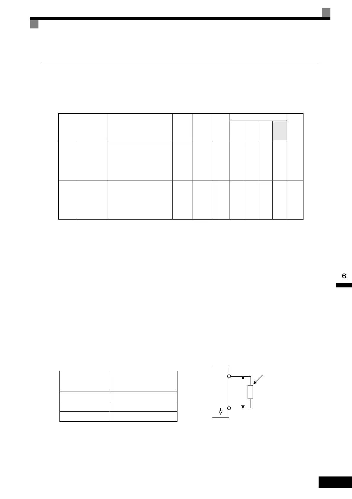
Using a Sourcing Output
Output Voltage
(Isolated)
VRL (V)
Load Impedance (kΩ)
+5 V min. 1.5 kΩ min.
+8 V min. 3.5 kΩ min.
+10 V min. 10 kΩ min.
Load impedance
MP
AC
VRL
 Loading...