Trial Operation Procedures
4-5
Basic Settings
Switch to the quick programming mode (the QUICK indicator on the Digital Operation should be lit) and then
set the following user constants. Refer to Chapter 3 Digital Operator and Modes for Digital Operator operat-
ing procedures and to Chapter 5 User Constants and Chapter 6 Constant Settings by Function for details on
the user constants.
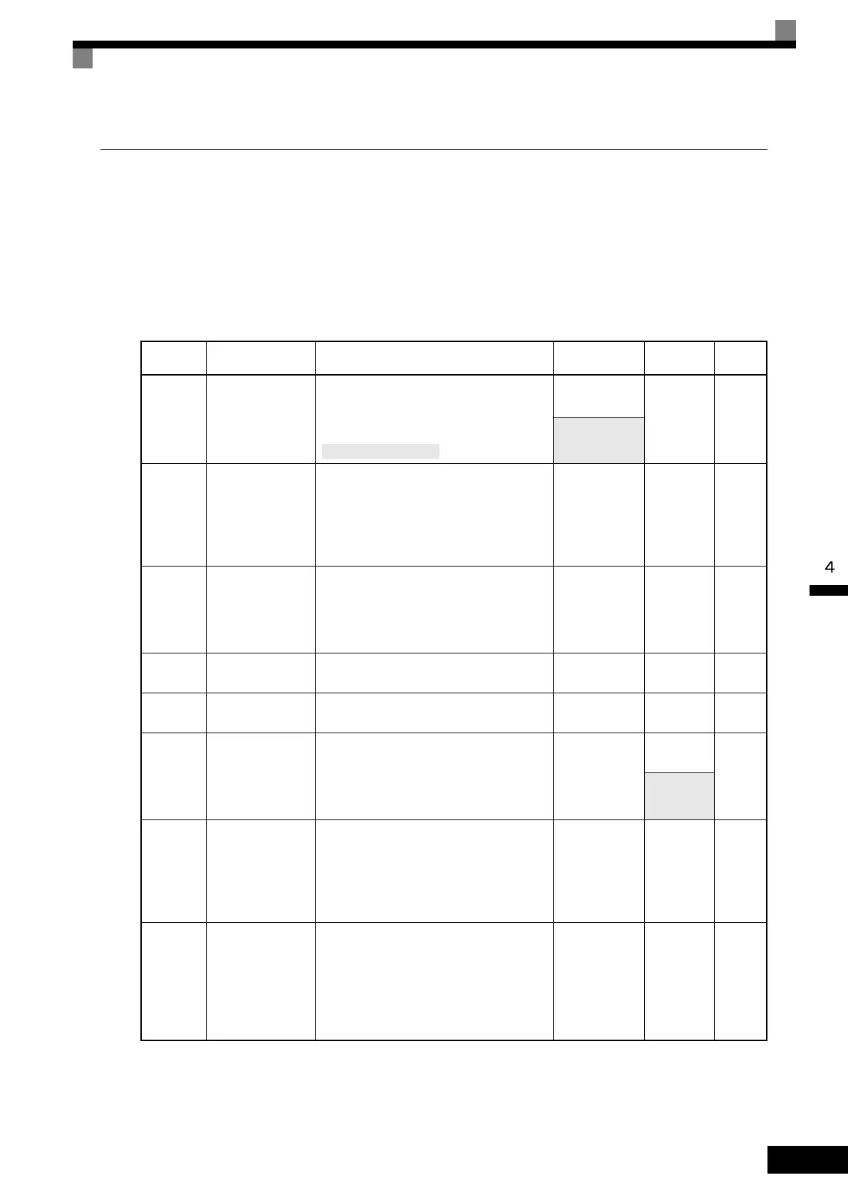
Constants that must be set are listed in Table 4.1 and those that are set according to the application are listed in
Table 4.2.
Table 4.1 Basic Settings of Constants
Constant
Number
Name Description Setting Range
Factory
Setting
Page
A1-02
Control method
selection
Set the control method for the Inverter.
0: V/f control
1: V/f control with PG
2: Open-loop vector control
0 to 2
05-8
0 to 3
b1-01 Reference selection
Set the frequency reference input method.
0: Digital Operator
1: Control circuit terminal (analog input)
2: MEMOBUS communications
3: Option board
4: Pulse train input
0 to 4 1
5-10
6-6
6-78
6-97
b1-02
Operation method
selection
Set the Run Command input method.
0: Digital Operator
1: Control circuit terminal (sequence input)
2: MEMOBUS communications
3: Option board
0 to 3 1
5-10
6-15
6-78
6-97
C1-01 Acceleration time 1
Set the acceleration time in seconds for the
output frequency to climb from 0% to 100%.
0.0 to 6000.0 s
*1
10.0 s
5-20
6-25
C1-02 Deceleration time 1
Set the deceleration time in seconds for the
output frequency to fall from 100% to 0%.
0.0 to 6000.0 s
*1
10.0 s
5-20
6-25
C6-01 CT/VT selection
Set to CT (not low noise, maximum current
overload: 150%) or VT (low noise, maxi-
mum current overload:120%).
0: CT
1: VT
0 or 1
1
*2
5-25
6-2
0
*2
E1-01
Input voltage set-
ting
Set the Inverter's nominal input voltage in
volts.
This setting is used as a reference value in
protection functions.
155 to 255 V
(200 V Class)
310 to 510 V
(400 V Class)
200 V
(200 V
Class)
400 V
(400 V
Class)
5-32
6-121
E2-01 Motor rated current Set the motor rated current.
10% to 200% of
Inverter's rated
current
Setting for
general-
purpose
motor of
same
capacity as
Inverter
5-34
6-60
6-119
3: Flux vector control
 Loading...