Wiring Examples
10-23
10
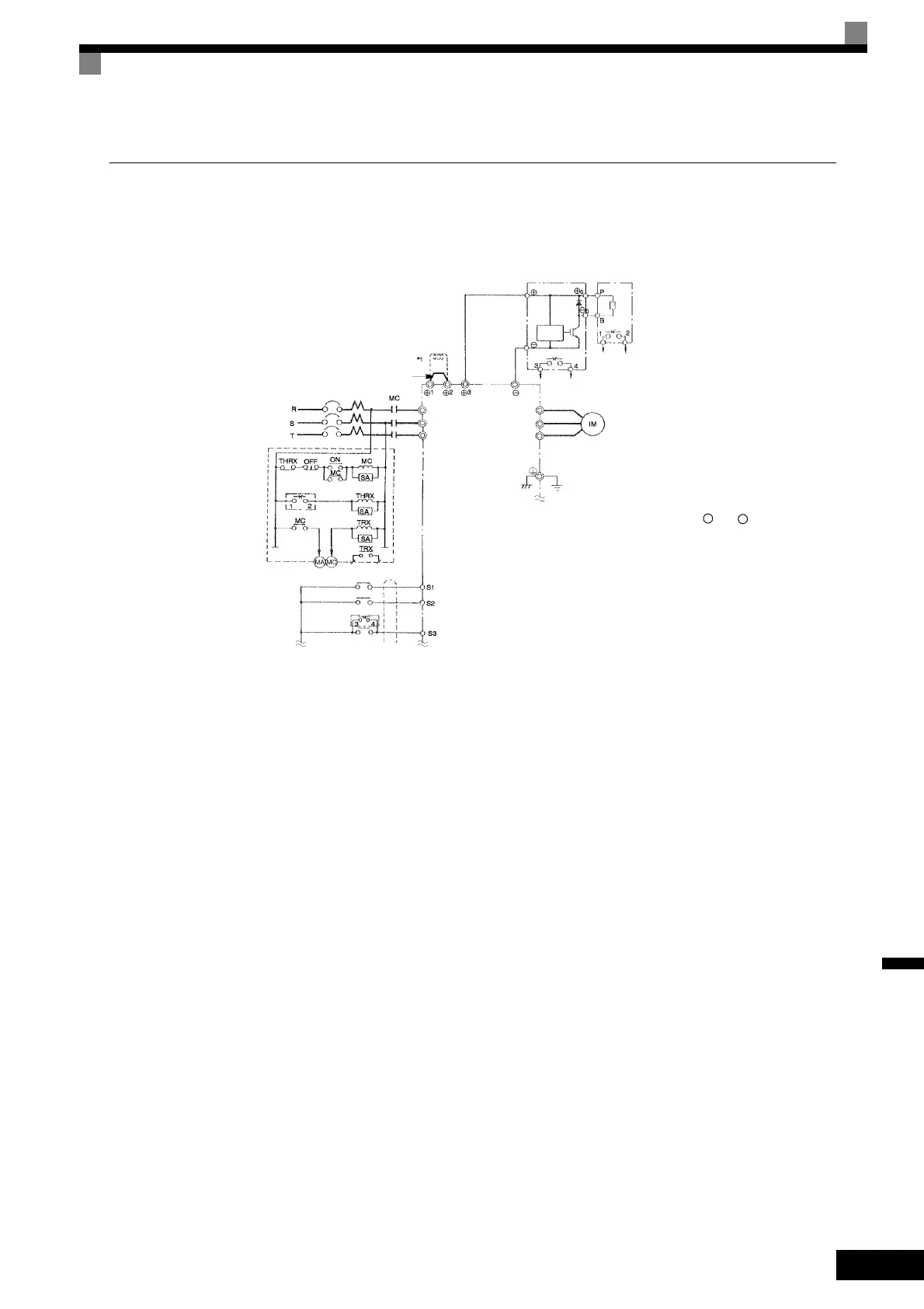
Using a Braking Unit and Braking Resistor Unit
This example shows wiring for a Braking Unit and Braking Resistor Unit.
CIMR-F7A2022, -F7A2030 (200 V Class Inverters of 22 kW, 30 kW)
Fig 10.10
3-phase power
200 to 230 V 50/60 Hz
A sequence is required to turn
OFF the power supply for the
thermal overload relay trip con-
tacts of the Braking Resistor
Unit.
DC Reactor to
improve input
power factor
(Optional)
Short-circuit bar
MCCB
Overload relay trip contact
of Braking Resistor Unit
Fault contacts
Braking Unit
(Optional)
Inverter
Motor
Level
detector
Braking Resistor Unit
*2
(Optional)
Braking Resistor overheating contacts
(Thermal overload relay trip contacts)
Ground to 100 Ω max.
* 1. Remove the short-circuit bar (normally connected) from + 1 and + 2 when connecting
a DC Reactor (Optional).
* 2. Disable stall prevention during deceleration by setting L3-04 and using a Braking
Resistor Unit. The motor may not stop within the deceleration time if this setting is
not changed.
Forward Run/Stop
Reverse Run/Stop
Braking Unit
External fault
Forward Run Command (forward run when ON)
Reverse Run Command (reverse run when ON)
R/L1
S/L2
T/L3
U/T1
V/T2
W/T3
Forward Run/Stop
 Loading...