2.4.4 Installation of position switch, axis 1 (option)
General
Position switches can be installed on axis 1. The position switches include cams
as shown in the figure below. The system parameter configuration must also be
updated.
The position switch sets may be delivered in one of two ways:
• Fitted by ABB on delivery. In this case, the cams must still be fitted and
locked by the user. For axis 1, the cover for the cams must also be fitted.
• As sets to be completely fitted to the robot and adjusted by the user.
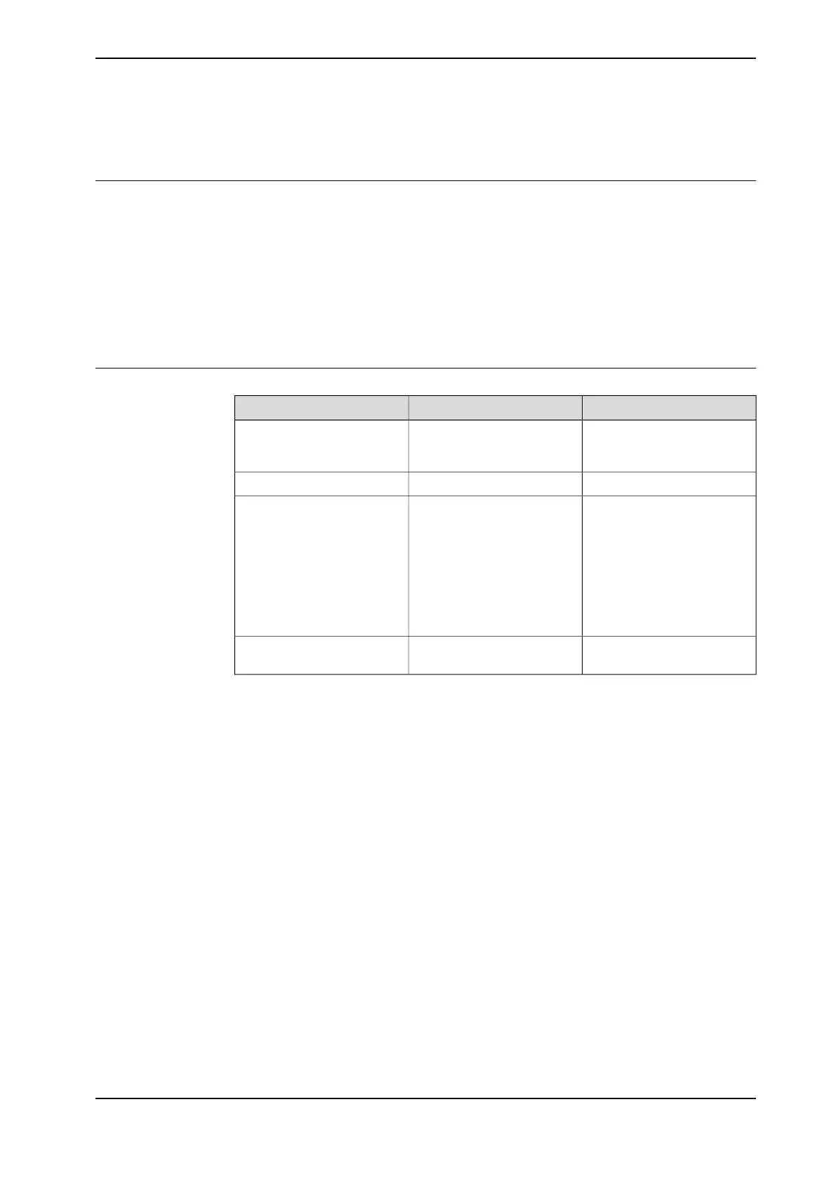
Required equipment
NoteArt.no.Description
Includes position switch and
plate for customer connec-
tions.
3HAC15715-1Position switch, axis 1
3HAC17252-1Connector kit R1.SW1
An additional connection
plate must be fitted to the ro-
bot base, if not already in-
stalled.
3HAC025778-001Plate set for customer connec-
tions
The plate differs from the
connection plate for customer
harness in regard to the geo-
metry of the R1.SW1 connect-
or interface.
-Additional cabling to and in-
side the controller
Continues on next page
Product manual - IRB 660 81
3HAC025755-001 Revision: W
© Copyright 2006-2020 ABB. All rights reserved.
2 Installation and commissioning
2.4.4 Installation of position switch, axis 1 (option)
 Loading...


