5 Installation and Commissioning
Product Manual, Control Cabinet IRC5P 3HNA009834-001 en Rev.06 117
5.8 Power Connections
5.8.3 Transformer Wiring
General Before connecting the robot to the mains power, it must be checked that the
transformer connection corresponds to the mains voltage to which the robot is to be
connected.
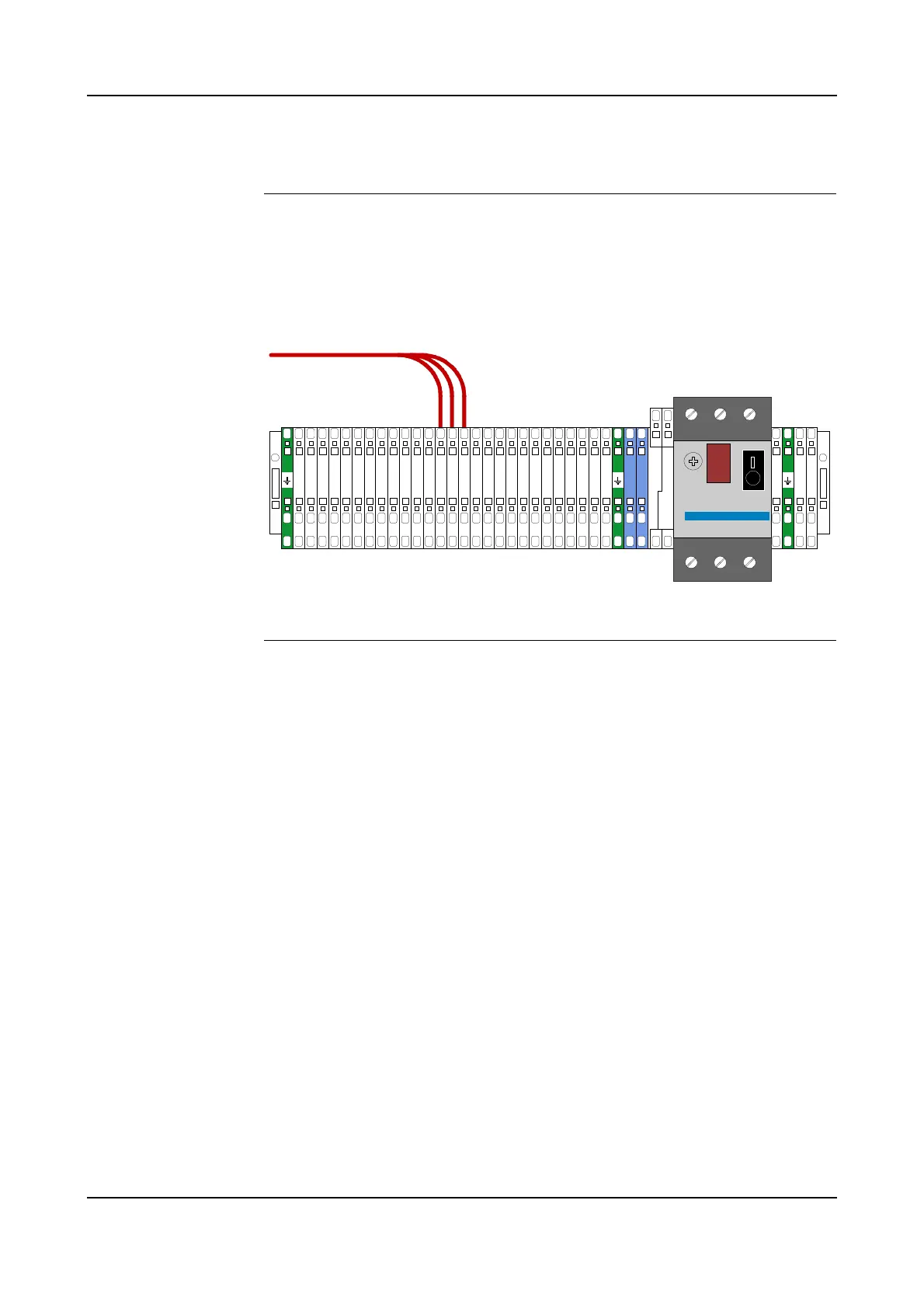
Figure 60 Transformer terminal board
Procedure This procedure describes how to check/change the connection of the transformer
and auto breaker setting.
1. Open the control cabinet front door.
2. Locate the transformer terminal board, located on the back wall inside the
controller as shown in ’Controller Connections Overview’ on page 42.
3. Check connection of transformer as shown in Figure 60.
4. If wiring is not correct, move wires for phase 1, 2 and 3 to correct terminal. For
information on tightening torque for terminal connections, see ’Tightening
Torques’ on page 216.
5. Check that supply overload protection is set to 16A.
Voltage rewiring terminal board.
Example shows wiring for 440V
Supply overload protection, FR2
To transformer
2
0
0
V
2
0
0
V
2
0
0
V
2
3
0
V
2
3
0
V
2
3
0
V
2
6
0
V
2
6
0
V
2
6
0
V
4
0
0
V
4
0
0
V
4
0
0
V
4
4
0
V
4
4
0
V
4
4
0
V
4
7
5
V
4
7
5
V
4
7
5
V
4
7
5
V
4
7
5
V
4
7
5
V
5
2
5
V
5
2
5
V
5
2
5
V
6
0
0
V
6
0
0
V
6
0
0
V
6
.
3
3
.
1
5
0
S
T
1
S
T
1

 Loading...


