7 Repair
Product Manual, Control Cabinet IRC5P 3HNA009834-001 en Rev.06 155
7.14 Replacement of Drive System 09 Components
7.14 Replacement of Drive System 09 Components
Location The drive units, consisting of motor drive units for the robot axis motors and
possible rectifier, are located on the back panel in the controller.
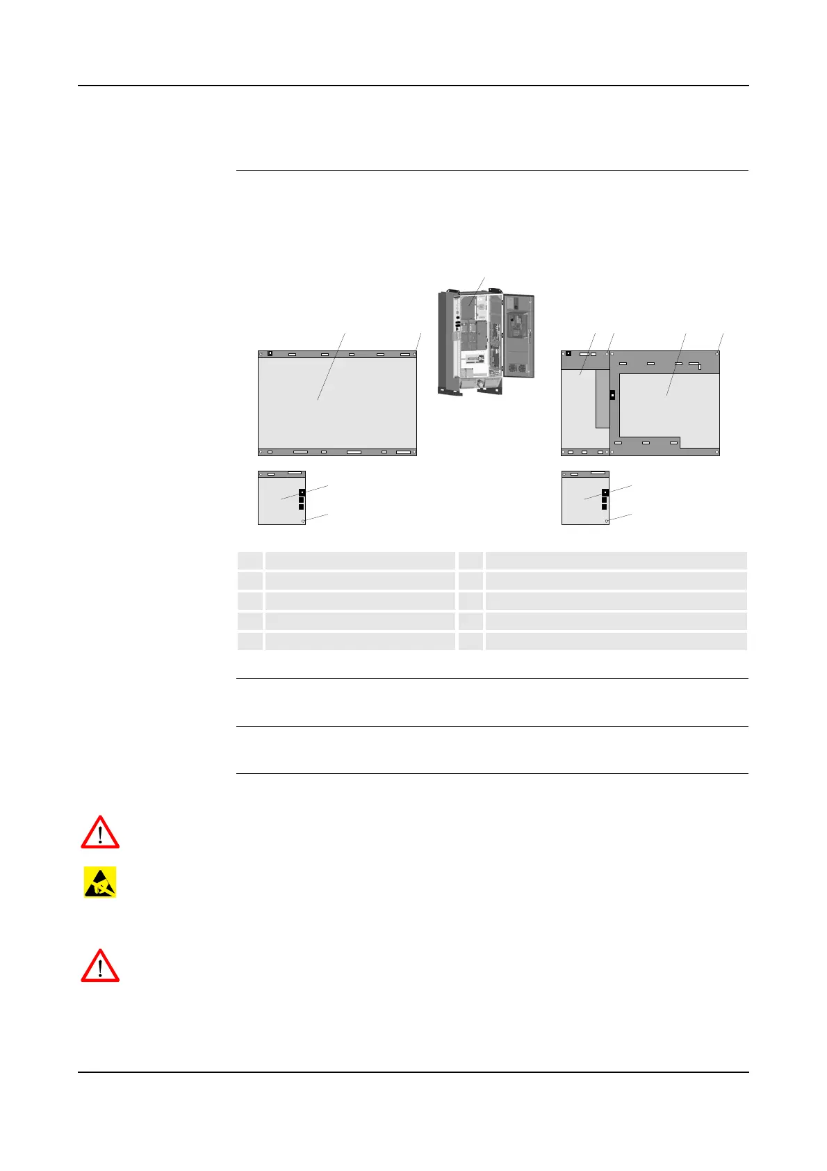
Figure 79 Motor drive unit assembly
References – For information on drive unit types etc, see ‘Unit Description, IRC5P’
Tools and Items – Hand tools
Removal The procedure describes how to remove a drive unit or the rectifier unit.
WARNING! No repair work must be performed on the robot before the safety
regulations in ’Safety’ on page 13 have been read and understood.
CAUTION! The unit is sensitive to ESD. Before handling the unit, please observe
the safety information in ’ESD Precautions’ on page 130.
1. Turn the electrical disconnect switch ‘off’ and lock switch in ‘off’ position.
WARNING! Make sure that the mains switch is ‘off’ and locked in ‘off’ position
before continuing. Also make sure that possible other connected systems are ‘off’.
2. Open controller front door and locate the unit to be replaced.
3. Remove connectors from the unit that shall be removed.
1 Motor drive unit assembly 6 Main drive unit MDU430A
2 Main drive unit MDU790A 7 MDU430A attachment screw
3 MDU790A attachment screw 8 Additional drive unit ADU
4 Additional rectifier unit ARU 9 ADU attachment screw
5 ARU attachment screw

 Loading...


