5 Installation and Commissioning
5.6 Encoder and Sync Switch Installation
90 3HNA009834-001 en Rev.06 Product Manual, Control Cabinet IRC5P
5.6.4 Connection Overview
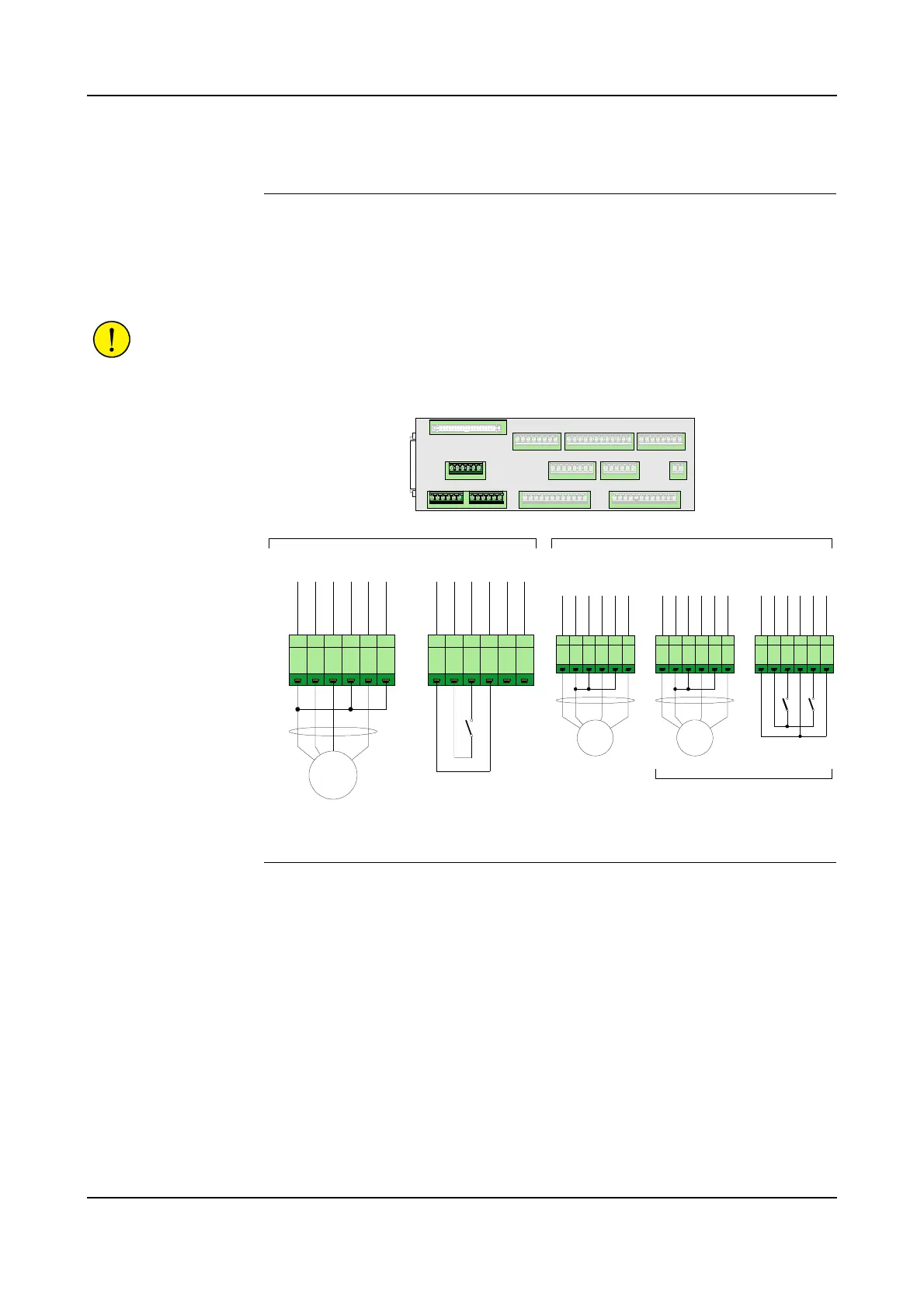
Connector Description The illustration below shows the connections for 1, 2 or 3 encoders and sync switch.
Connections are made on the Safety Connection Board, SCB.
Connections for conveyor tracking will normally consist of one PNP encoder
connected to connector X5 and one sync switch connected to connector X7.
CAUTION! To avoid interference to encoder signals, 4 wire twisted pair screened
cables must be used for encoder connections.
Figure 38 Encoder and Sync Switch connection
Options The encoder inputs support both PNP and NPN type encoders. Optionally an NPN
encoder can be installed. Optionally connector X7 may be used for a third encoder
or for connection of a second sync switch, as shown in the illustration.
The optional components must be configured explicitly.
Note: The system supports 24VDC encoders. If RS422 encoders are used, a signal
converter such as BLE-01 must be used.
Extra encoders can be used for a second conveyor, a backup encoder, or for
monitoring of paint flow e.g. when using Küppers initiators. For more information
on monitoring paint flow, refer to the gear flow meter in the ‘Unit Description,
Paint’ manual.
X5 X6 X2 X1
X3 X13 X4
X8 X9 X10
X11
X12
X7
SCB-01
1 2 3 4 5 6
+
2
4
V
D
C
G
N
D
E
N
C
_
1
A
+
E
N
C
_
1
A
-
E
N
C
_
1
B
+
E
N
C
_
1
B
-
PNP
Encoder 1
X5
1 2 3 4 5 6
+
2
4
V
D
C
G
N
D
P
_
S
T
A
R
T
_
0
1
+
P
_
S
T
A
R
T
_
0
1
-
P
_
S
T
A
R
T
_
0
2
+
P
_
S
T
A
R
T
_
0
2
-
Sync Switch 1
X7
1 2 3 4 5 6
+
2
4
V
D
C
G
N
D
E
N
C
_
2
A
+
E
N
C
_
2
A
-
E
N
C
_
2
B
+
E
N
C
_
2
B
-
1 2 3 4 5 6
+
2
4
V
D
C
G
N
D
E
N
C
_
3
A
+
E
N
C
_
3
A
-
E
N
C
_
3
B
+
E
N
C
_
3
B
-
Encoder 3
X6 X7
NPN
1 2 3 4 5 6
+
2
4
V
D
C
G
N
D
P
_
S
T
A
R
T
_
0
1
+
P
_
S
T
A
R
T
_
0
1
-
P
_
S
T
A
R
T
_
0
2
+
P
_
S
T
A
R
T
_
0
2
-
Sync Switch 1
X7
Sync Switch 2
Encoder 3 or
Sync Switch(es) connection
Encoder 2
NPN
OptionsStandard conveyor connections

 Loading...


