7 Repair
Product Manual, Control Cabinet IRC5P 3HNA009834-001 en Rev.06 161
7.17 Replacement of Brake Resistor Bleeders
7.17 Replacement of Brake Resistor Bleeders
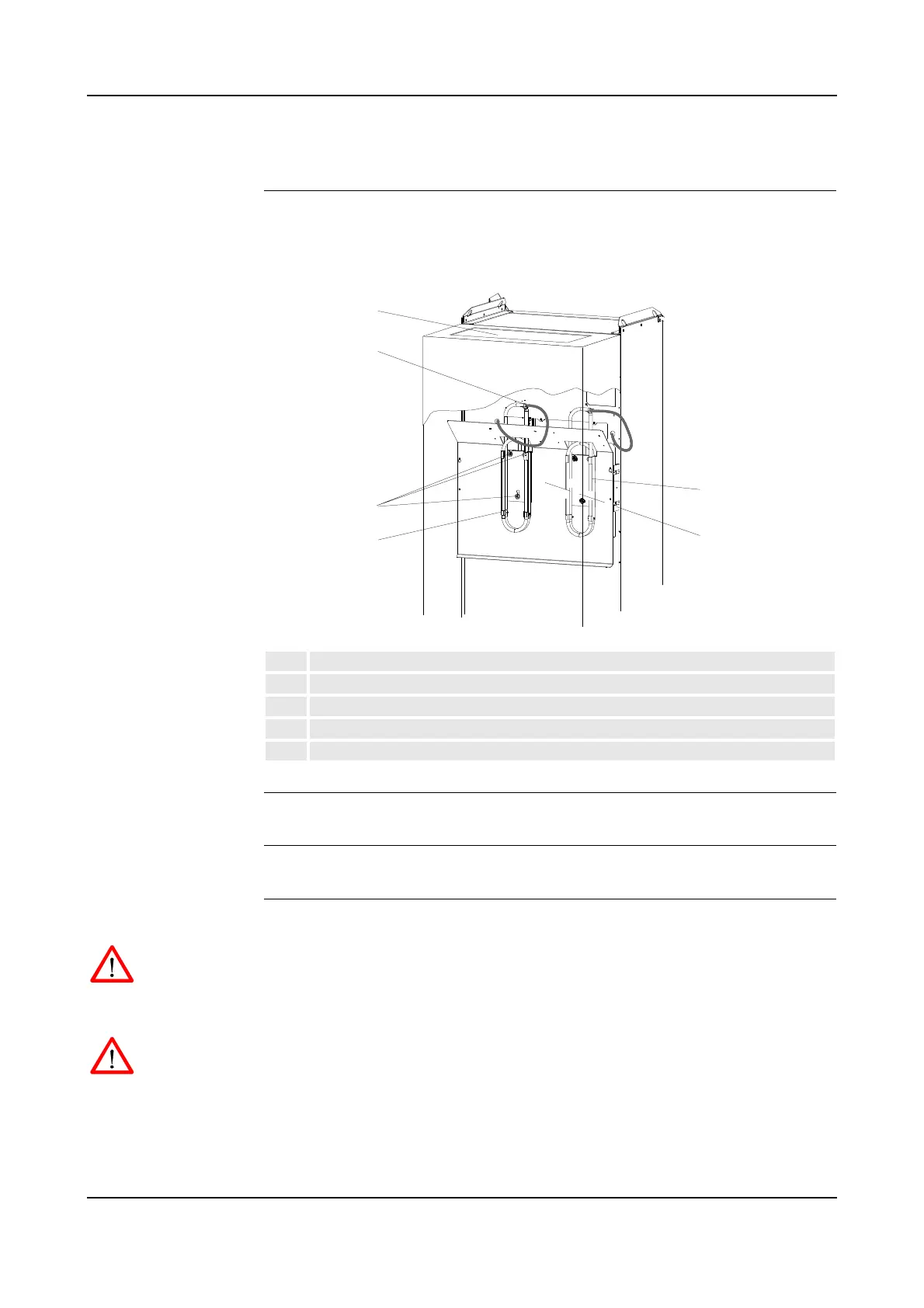
Location One or two Brake Resistor Bleeders are located on the rear side of the controller as
shown below.
Figure 82 Brake resistor bleeders, controller rear view
References – ’Replacement of Servo Fan Unit’ on page 159
Tools and Items – Hand tools
Removal The procedure describes how to remove the brake resistor bleeders.
WARNING! No repair work must be performed on the robot before the safety
regulations in ’Safety’ on page 13 have been read and understood.
1. Turn the electrical disconnect switch ‘off’ and lock switch in ‘off’ position.
WARNING! Make sure that the mains switch is ‘off’ and locked in ‘off’ position
before continuing. Also make sure that possible other connected systems are ‘off’.
2. Remove servo fan unit as described in ’Replacement of Servo Fan Unit’ on
page 159.
1 Brake resistor bleeder 1
2 Servo fan unit access hole
3 Attachment screws and slots
4 Connector (inside cabinet)
5 Location for brake resistor bleeder 2 (used for pumps or CBS)

 Loading...


