5 Installation and Commissioning
Product Manual, Control Cabinet IRC5P 3HNA009834-001 en Rev.06 77
5.4 Robot Safety System Connections
5.4.6 Emergency Brake Release Switch
General A switch may be installed to enable releasing the axis brakes for the robot in an
emergency situation. This may be a situation where a person is trapped by the robot
arm and brakes can not be released quickly by normal means, e.g. at power failure
or the pendant is not at hand.
Installation The emergency brake release switch should be a switch installed behind a breakable
glass (like a fire alarm) to prevent the switch from being used for normal brake
release purposes. The switch must be marked with a warning sign informing that
using the switch will violate the spray booth explosion safety functions.
The switch must be placed in a convenient location outside the spray booth with a
clear view of the robot.
WARNING! The emergency brake release switch will apply 24VDC to the axis
brakes even if the purge system is not active and must only be used in emergency
situations.
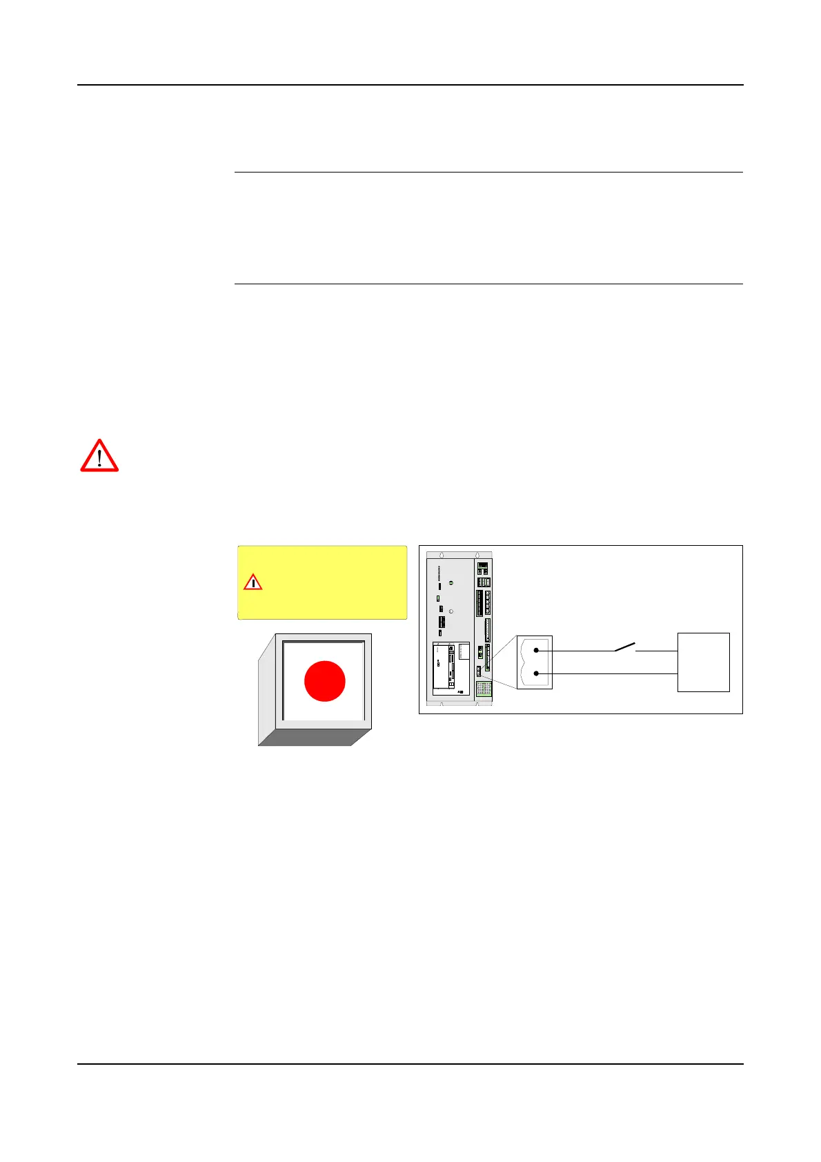
Figure 33 Emergency brake release switch design and connection
A 24VDC power supply, capable of supplying minimum 4 Ampere is required for
this function. If the switch is to work also by power failure, the power supply must
be battery backed.
1. Install a normally open switch and 24VDC power supply between pin 1 and 2
in connector X24 on the PDB board as shown in the figure above.
2. Install switch element inside a box with a breakable glass.
3. Make a sign similar to the one shown in the illustration and place it above or
beside the switch.
Brake glass and push switch
to release axis brakes.
Using the switch will violate the
cabin explosion safety system
WARNING
GND
+24VDC
Emergency brake
release switch
Emergency brake release switch
24VDC
power supply
X20X21
X4
X9 X8
X12 X13 X10
X6
X7
X11
X14
X15
X1
X16
X17
X18
PDB-01
X23
X2
X3
X5
X40
X25
X24
X20X21
X4
X12 X13 X10
X
6
X
7
X
1
1
X
1
4
X
1
5
X
1
6
X
1
7
X
1
8
X
2
3
X2
X3
X5
X40
X25
X24
X9 X8
X1
X4
X9 X8
X10
X6
X7
X11
X14
X15
X1
X12 / X13
X5
X2
X3
LEDS
AC
TEMP
PC
SYS
I/O
FAN
BRAKE
ULTRA CAP
HV
LEDS PDB- 01
X18
X23
X20
X16
X17
X25
X24
X21
POWER DISTR IBUTION BO ARD
PDB-01
ABB AS, Robotics
1
2
PDB-X24

 Loading...


