5 Installation and Commissioning
Product Manual, Control Cabinet IRC5P 3HNA009834-001 en Rev.06 67
5.4 Robot Safety System Connections
5.4.3 Safety System Connection Overview
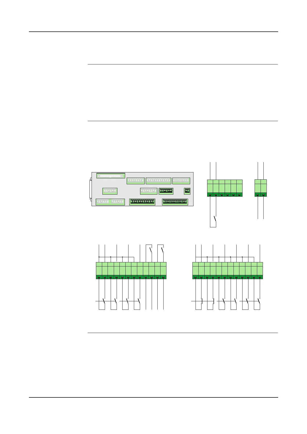
General The following gives an overview of the connections needed for the safety system.
The connections are performed by removing links in the safety connectors and
install 2 pole switches in their place.
The safety system can also be set up for test run as described in section ’Connecting
Safety System for Test’ on page 69.
Connection Overview The illustration below shows the connections for the emergency stop chain and run
chain.
Figure 29 Safety system connections
Procedure 1. The emergency stop chain is as default connected for Internal +24VDC Supply.
If it is required to have the emergency stop chain operative when the robot is
switched ‘off’, the chain may be connected to External +24VDC Supply as
described in section ’Emergency Stop Chain Supply’ on page 70.
2. If required, install Emergency Stop Switch(es) (Category 0) in addition to the
Emergency Stop Switches on the main panel and pendant. For information, see
1 2 3 4 5 6
1 2 3 4 5 6 7 8 9 10 11 121 2 3 4 5 6 7 8 9 10 11 12
X4
+
2
4
V
_
E
M
Y
X5 X6 X2 X1
X3 X13 X4
X8 X9 X10
X11
X12
X7
SCB-01
E
X
T
_
T
M
S
1
E
X
T
_
T
M
S
2
E
X
T
_
E
S
1
E
X
T
_
E
S
2
E
X
T
_
A
M
S
1
E
X
T
_
A
M
S
2
Emergency
Stop (Cat.0)
Test Mode
Stop (Cat.0)
Auto Mode
Stop (Cat.0)
E
X
T
_
G
M
S
1
E
X
T
_
G
M
S
2
E
X
T
_
D
S
1
E
X
T
_
D
S
2
K
A
1
1
K
A
1
5
+
2
4
V
D
C
+
2
4
V
D
C
C
h
1
C
h
2
C
h
1
C
h
2
C
h
1
C
h
2
X2 X1
Ext Emy Stop
Chain Supply
X13
E
X
T
_
E
S
_
R
S
T
+
2
4
V
D
C
General Mode
Stop (Cat.0)
Delayed
Stop (Cat.1)
Emy Stop
Feedback
C
h
1
C
h
2
C
h
1
C
h
2
C
h
1
C
h
2
Emy Stop Reset
G
N
D
1 2
+
2
4
V
D
C
G
N
D

 Loading...


