7 Repair
Product Manual, Control Cabinet IRC5P 3HNA009834-001 en Rev.06 143
7.8 Replacement of Computer Unit
7.8 Replacement of Computer Unit
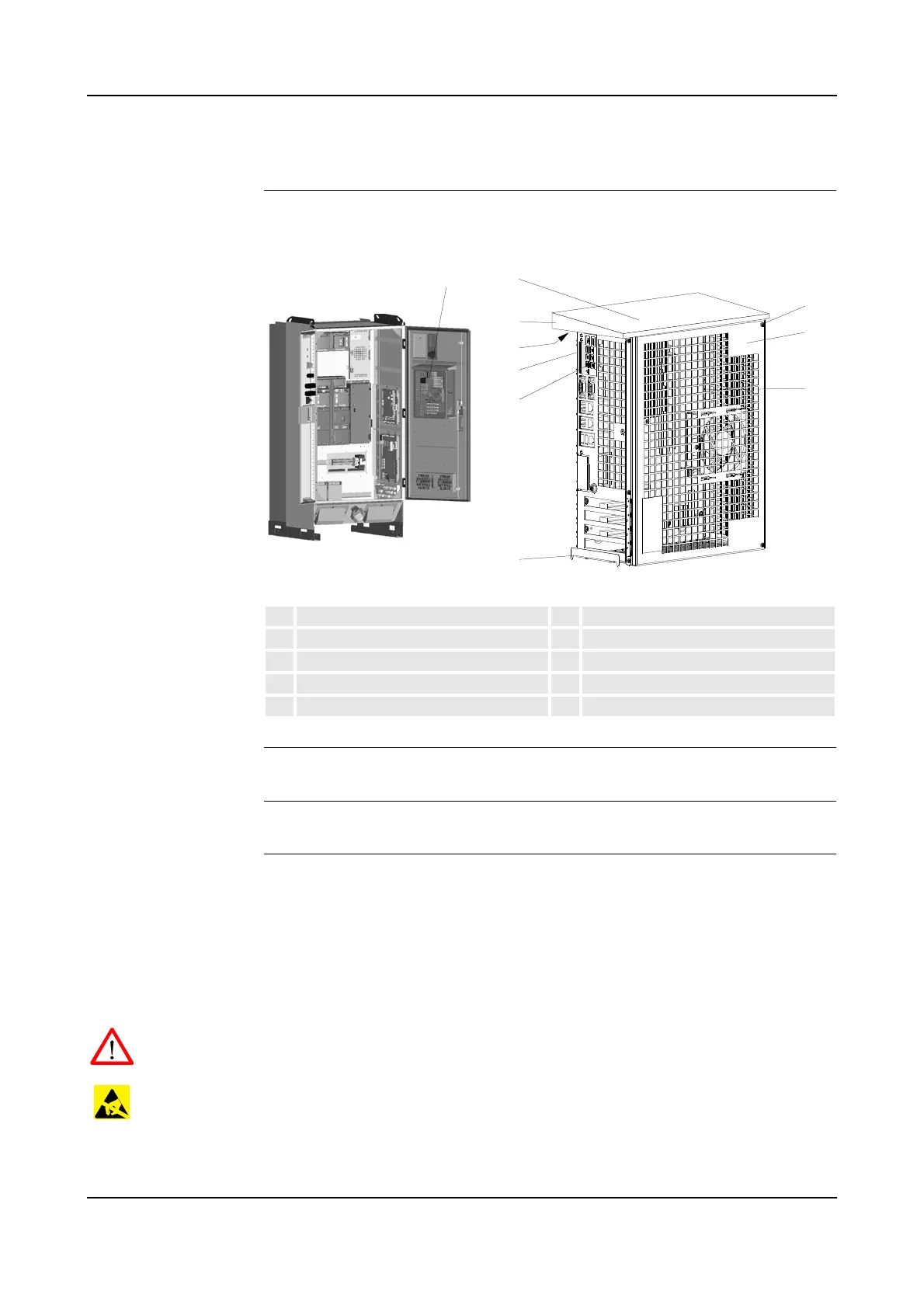
Location The Computer Unit is located on the inside of the controller door as shown below.
Figure 73 Computer unit
References – ’Replacement of Compact Flash’ on page 151
Tools and Items – Hand tools
Removal The procedure describes how to remove the complete computer unit, either to
replace the unit itself, or for replacing components inside the computer unit.
Note: For all procedures describing replacement of internal components, the
computer unit cover needs to be removed. This is performed by removing 4
attachment screws (73/4), lift off the cover (73/3) and disconnect the fan connector
(73/6).
WARNING! No repair work must be performed on the robot before the safety
regulations in ’Safety’ on page 13 have been read and understood.
CAUTION! The unit is sensitive to ESD. Before handling the unit, please observe
the safety information in ’ESD Precautions’ on page 130.
1. Turn the electrical disconnect switch ‘off’ and lock switch in ‘off’ position.
1 Computer Unit 6 Cover attachment screws
2 Computer unit top cover 7 Connectors
3 Top cover attachment screws 8 Cooling fan connector
4 Attachment hooks 9 Compact Flash card
5 Computer unit cover

 Loading...


