3 System Description
Product Manual, Control Cabinet IRC5P 3HNA009834-001 en Rev.06 21
3.2 Basic Design
3.2.3 Cabinet Labelling
General Following naming conventions should be noted when working with the controller.
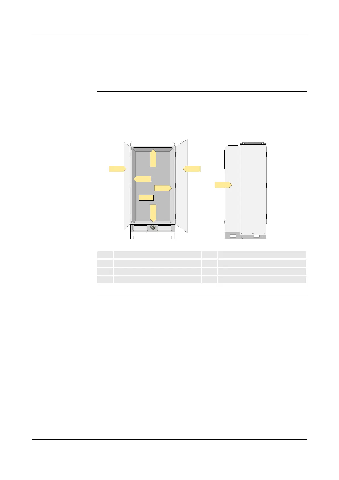
Control Cabinet Panels The different components, connectors and terminal boards are located on the cabinet
back wall and side wall etc. Each of these panels are labelled AC1, AC2, etc. as
described below.
Figure 4 Control cabinet panels
Connection Labelling Connectors are labelled X1, X2, etc., and terminal boards are labelled XT1, XT2,
etc.
A connector or terminal board located on one of the cabinet panels is labelled with
the designation of the panel in addition to the name of the connector (or terminal
board), e.g. +2-XT1 which means terminal board XT1 located on the cabinet back
wall AC2.
A connector or terminal board located on one of the units in the cabinet is labelled
with the name of the unit in addition to the name of the connector (or terminal
board), e.g. MIB-X22 which means connector X22 on the MIB unit.
AC1 Panel door AC5 Right side wall
AC2 Back wall AC6 Left side wall
AC3 Bottom plate AC7 Top plate
AC4 Front door AC8 Cabinet rear side

 Loading...


