GUID-795A6797-D4D9-4705-A496-C3FBD771C211-ANSI V1 EN
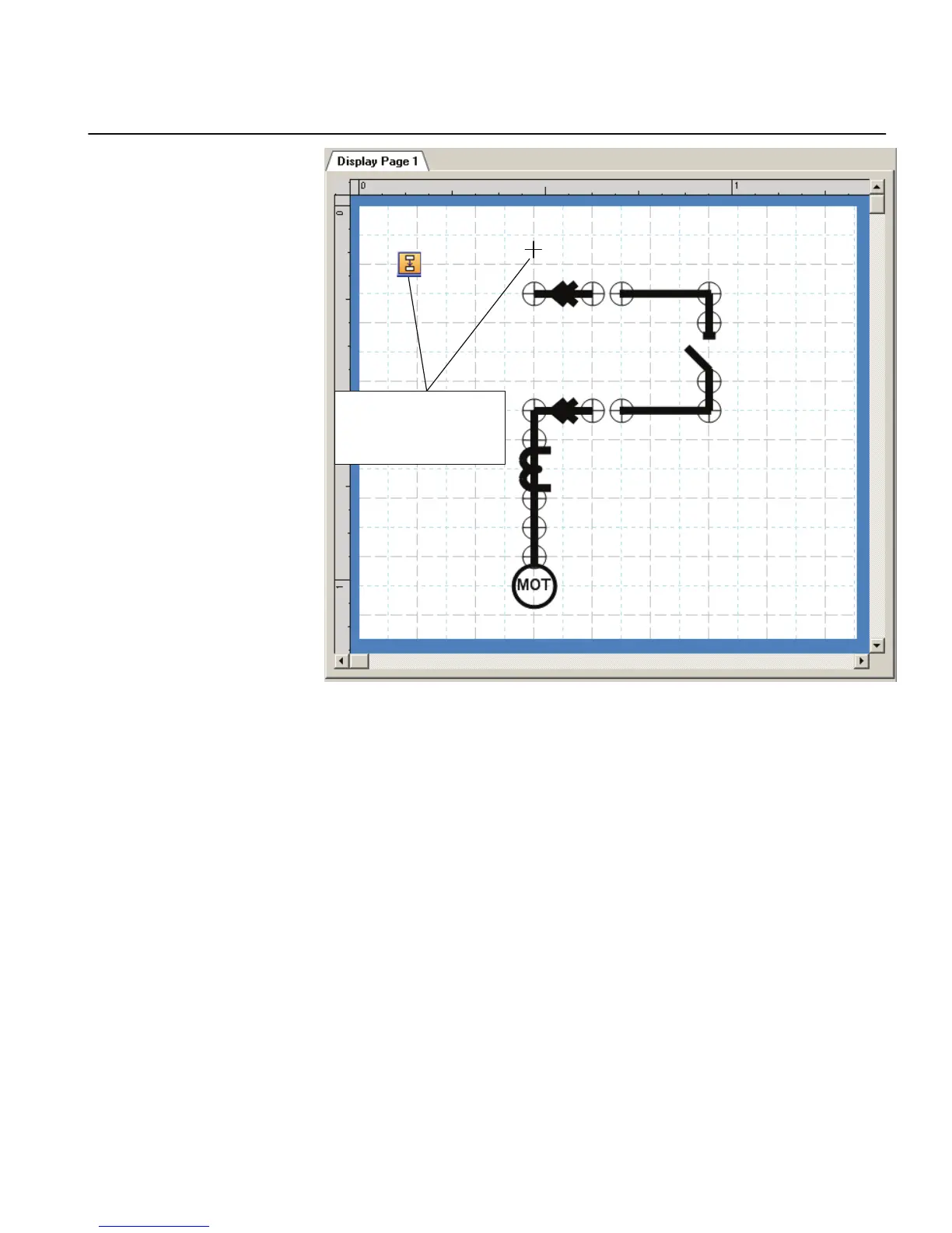
Figure 56: Graphical Display Editor: drawing a line between symbols
4. Draw all the necessary line elements.
5. To finish the line drawing, click Select on the menu bar.
6.1.2 Bay configuration engineering
A view with a single-line diagram and measurements contains active living objects.
The object values are updated by the IED periodically (measurement) or in case of an
event.
Once the symbols are placed on the HMI page, they must be linked to the
corresponding function block in the application configuration, which protects or
controls the object that the symbol on the HMI page represents.
1MRS240044-IB A Section 6
LHMI engineering
REF615R 93
Engineering Manual
 Loading...