GUID-805CB8E5-0BF2-409D-802C-57DC95659075 V1 EN
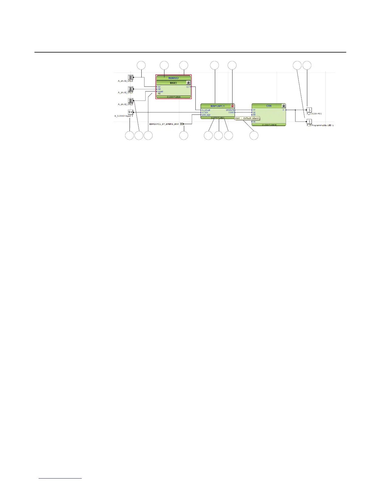
Figure 35: Application Configuration tool: function block overview
1. Connection(s)
2. User-defined function block name
3. Function block, selected (red)
4. Function block name
5. Function block, locked (red)
6. Hardware, binary output channel
7. Hardware, programmable LED
8. Hardware, binary input channel
9. Hardware, analog input channel
10. User-defined signal name
11. User-defined input variable
12. Execution order
13. Cycle time
14. Instance number
15. Signal description note
5.1.2 Signals and signal management
Function block has a set of input and output signals. The placement of function block
signals is from left to right. Input signals are placed on the left and output signals on
the right.
Function blocks can contain more signals than needed in that application part. Unused
signals can be hidden to get a clear picture.
Signals are located up and down on both sides of the middle position. When there is
space left, some signals may be moved up or down for better visibility and connection
routing.
1MRS240044-IB A Section 5
Protection and control engineering
REF615R 63
Engineering Manual
 Loading...