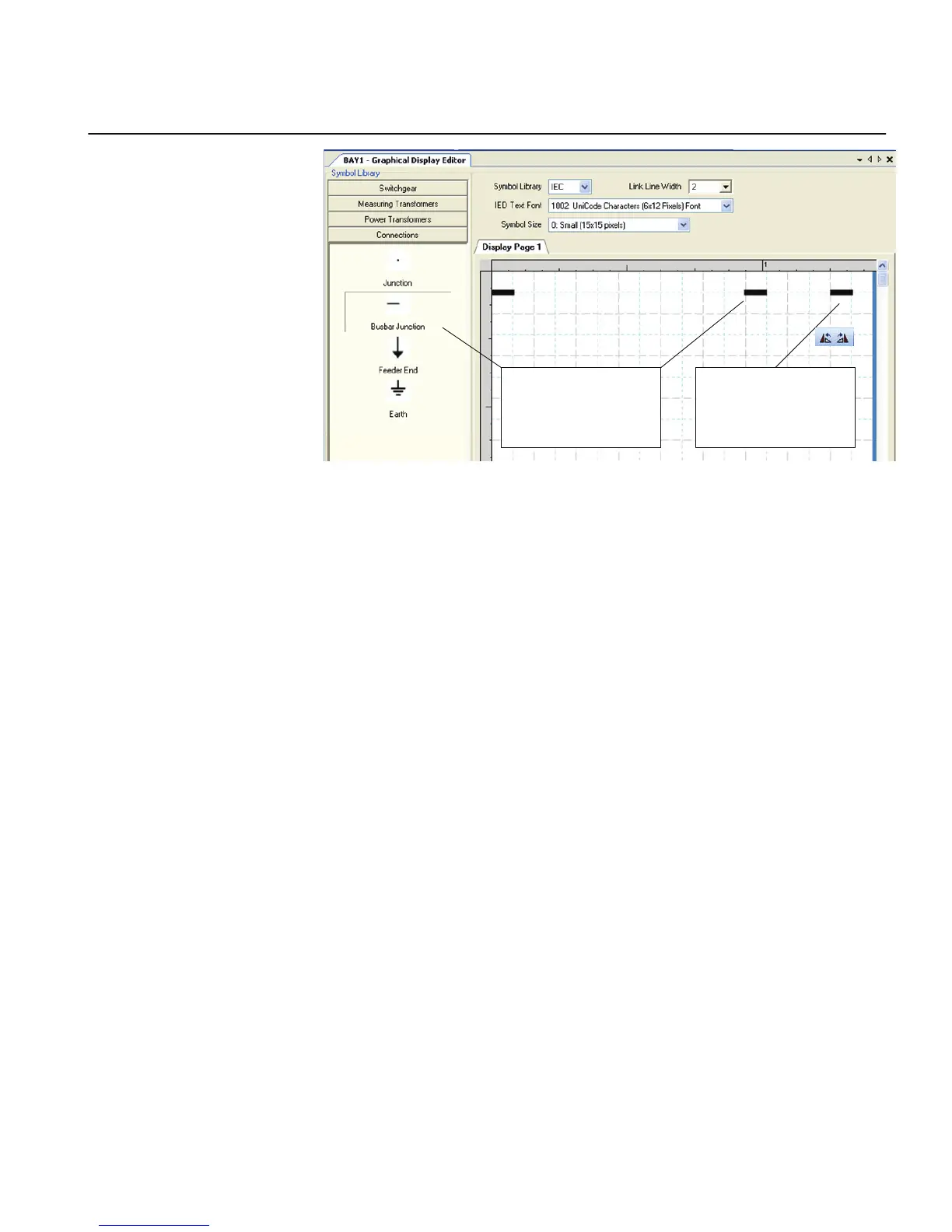
Place Busbar Junctions into
display page
Select Busbar Junction
symbol and use Rotate
command from toolbar to get
the busbar end to the margin
GUID-A58439A5-575C-4EED-A5A9-77FDECAA9D21 V1 EN
Figure 54: Graphical Display Editor: drawing a busbar and placing busbar
junctions
3. Add a link between one Busbar Junction point and the corresponding symbol or
junction point.
6.1.1.10 Adding symbols into a display page
1. Prepare the body of the single-line diagram by locating symbols to the wanted
positions on the display.
2. Drag the apparatus or transformer symbols into a raster box.
3. Drag the connection symbols into a raster box.
4. Place the junction points.
Do not connect two symbols directly to each other. Instead, add a junction
between them.
5. Use the X and Y coordinates in the Object Properties window to adjust the
placement of symbols in the single-line diagram.
1MRS240044-IB A Section 6
LHMI engineering
REF615R 91
Engineering Manual
 Loading...