GUID-BF9C2038-2E24-4530-B9DF-8448E535F9EC V1 EN
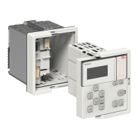
Figure 73: Single-line diagram with several buttons. The CNT_LOGIC
button is in “On” state and the SW_MODE button is selected
and it is currently in “Off” state
The selected button has a square around it.
2.
Press
or to control the selected button.
The control position of the protection relay affects the controlling
SLD buttons. Depending on the parameter settings, the protection
relay may have to be in local state for the control to succeed.
6.2.1.3 Controlling single-line diagram tap changer
1.
Select the tap changer with or if it is not already selected.
The selected object has a square around it.
2.
Press
to start controlling the tap changer.
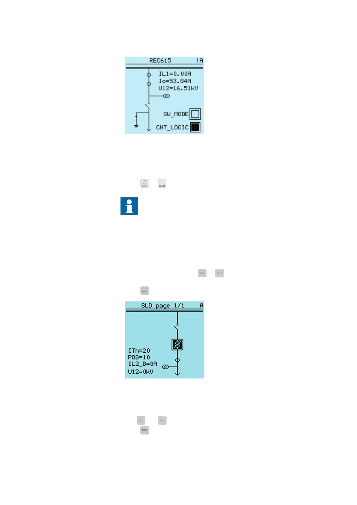
GUID-1859C00F-9B4A-4497-889C-EE7A33B9810A V1 EN
Figure 74: Single-line diagram with tap changer symbol. Inverted tap
changer symbol indicates that it can be controlled using arrow
keys.
3.
Use and to raise or lower the tap changer position.
4.
Press to end the controlling.
1MRS758754 B Section 6
Operating procedures
REC615 and RER615 95
Operation Manual
 Loading...