Rockwell Automation Publication 750-IN001O-EN-P - October 2014 121
Lift and Mount the Drive Chapter 3
Fiber-Optic Cables
Disconnect Drive Control Pod
Wiring Connections
Frame 8 drives, with drive control pod installed, complete steps 1 and 2 of this
procedure.
Frame 9 and larger drives, with drive control pod installed, complete steps 1
through 7 of this section.
If the drive control pod is mounted remotely, skip this section.
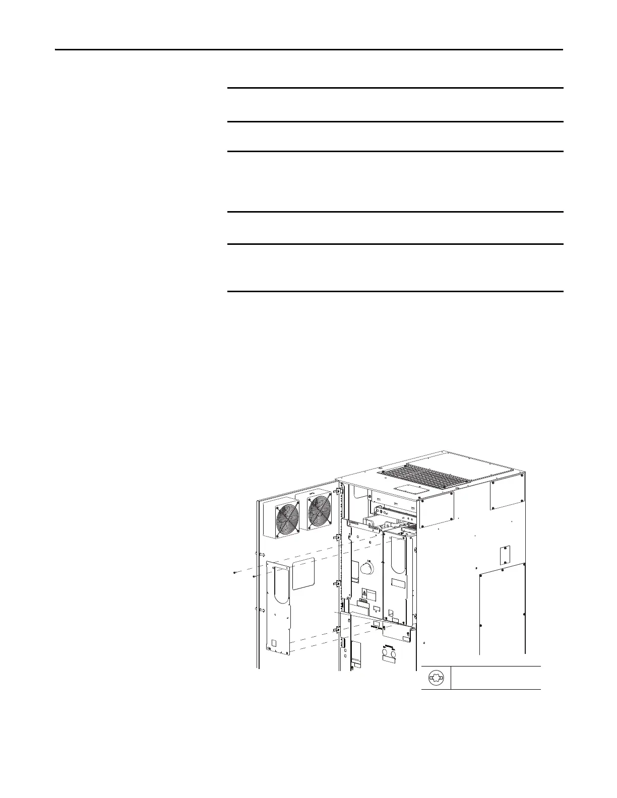
1. Remove the right front cover.
Fiber-optic cables have a minimum bend radius of 50 mm (2 in.). If cables are
over bent, damage will occur.
For Frame 8 drives, the fiber-optic cables used to connect the fiber interface
board to both the converter (AC Input) / DC precharge (DC Input) control board
and the inverter power layer interface board must be the same length. The
cables provided are 560 mm (22 in.) in length.
For Frame 9 and larger drives, the fiber-optic cables used to connect the fiber
interface board to the power layer interface board must be the same length.
The cables provided are 2.8 m (110 in.) in length.
T20 or F 6.4 mm (0.25 in.)
1.8 N•m (16.0 lb•in)
Floor Mount Frame 8 Shown

 Loading...


