230 Rockwell Automation Publication 750-IN001O-EN-P - October 2014
Chapter 5 I/O Wiring
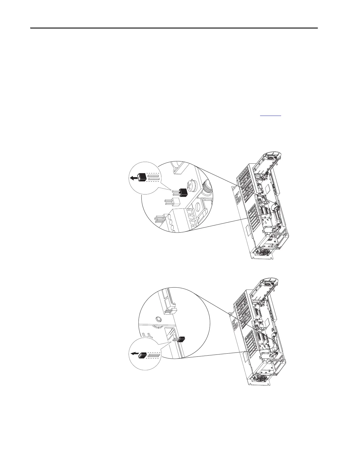
Hardware Enable Circuitry
Each main control board has one digital input, Digital Input 0, that can be used
as a general purpose programmable input, or by removal of a jumper, configured
as a dedicated hardware enable, which is unaffected by parameter settings.
• PowerFlex 753 - Digital Input 0 is found on TB3
• PowerFlex 755 - Digital Input 0 is found on TB1
To configure Digital Input 0 as a dedicated hardware enable, complete the
following steps.
1. Access the control pod as described beginning on page 222
.
2. Locate and remove ENABLE Jumper on the Main Control Board (see
diagram).
Figure 121 - PowerFlex 753 - ENABLE Jumper Location
Figure 122 - PowerFlex 755 - ENABLE Jumper Location (Wall Mount Frames 1…7)

 Loading...


