266 Rockwell Automation Publication 750-IN001O-EN-P - October 2014
Chapter 5 I/O Wiring
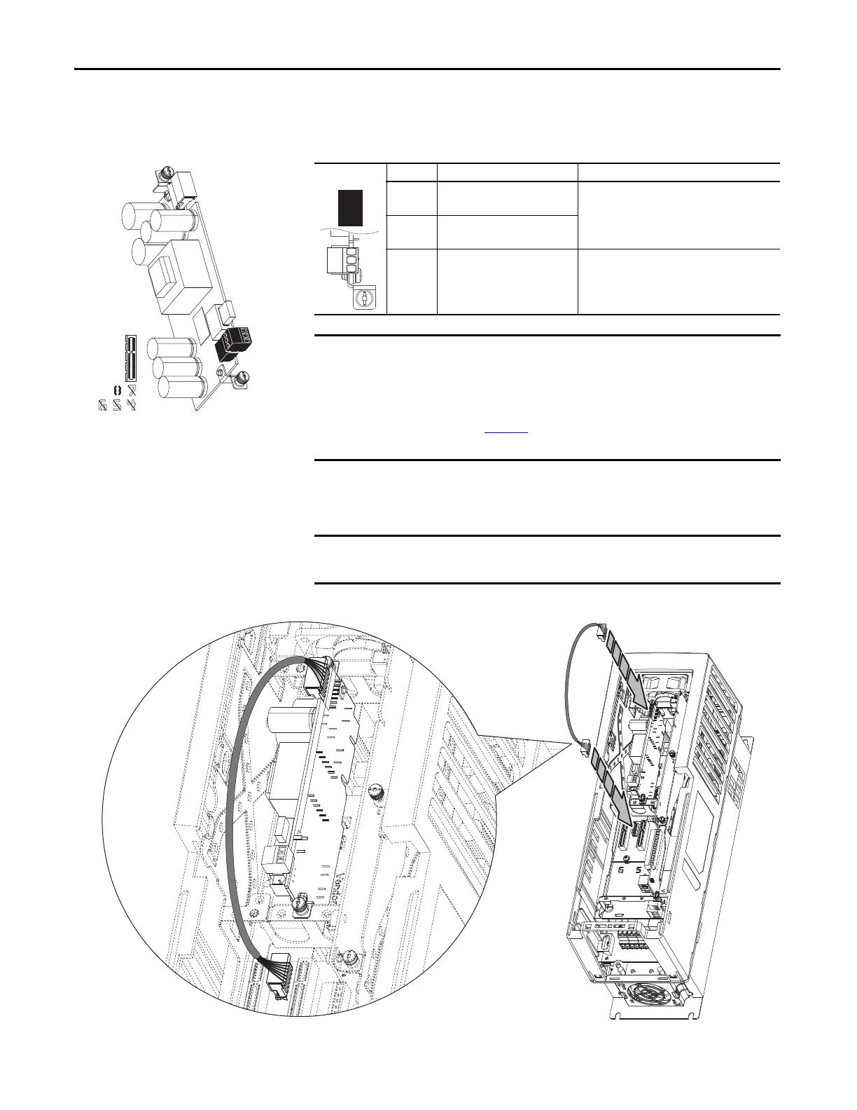
Auxiliary Power Supply Option Module
Table 66 - TB1 Terminal Designations
A connector cable is provided with Auxiliary Power Supply option modules for
use in PowerFlex 753 drives. The cable is used to connect the module to the
backplane when installed on the upper control pod brackets.
Figure 133 - Auxiliary Power Supply Installation in PowerFlex 753 Drive (All Frames) and
PowerFlex 755 (Frame 1 Drives Only)
20-750-APS
Terminal Name Description
AP+ +24 Volt Auxiliary Power Connections for customer supplied power supply:
24V DC ±10%, 3 A, PELV (Protective Extra Low
Voltage) or SELV (Safety Extra Low Voltage)
AP– Auxiliary Power Common
Sh Shield Terminating point for wire shields when an EMC
plate or conduit box is not installed.
The Auxiliary Power Supply option module may be installed in any option port.
Due to its size, the module will extend over and block an adjacent port.
Therefore, installation in Port 8 is recommended.
Do not use the Auxiliary Power Supply option module with Frame 8 and larger
drives. Refer to page 233
for information on connecting an external power
supply to Frame 8 and larger drives.
The connector cable is used with PowerFlex 755 Frame 1 drives. The cable is not
used with PowerFlex 755 Frame 2 and larger drives.
AP+
AP–
Sh
AP+
AP-
Sh

 Loading...


