Rockwell Automation Publication 750-IN001O-EN-P - October 2014 239
I/O Wiring Chapter 5
Uninterruptible Power
Supply Connections -
Common DC Input Drives
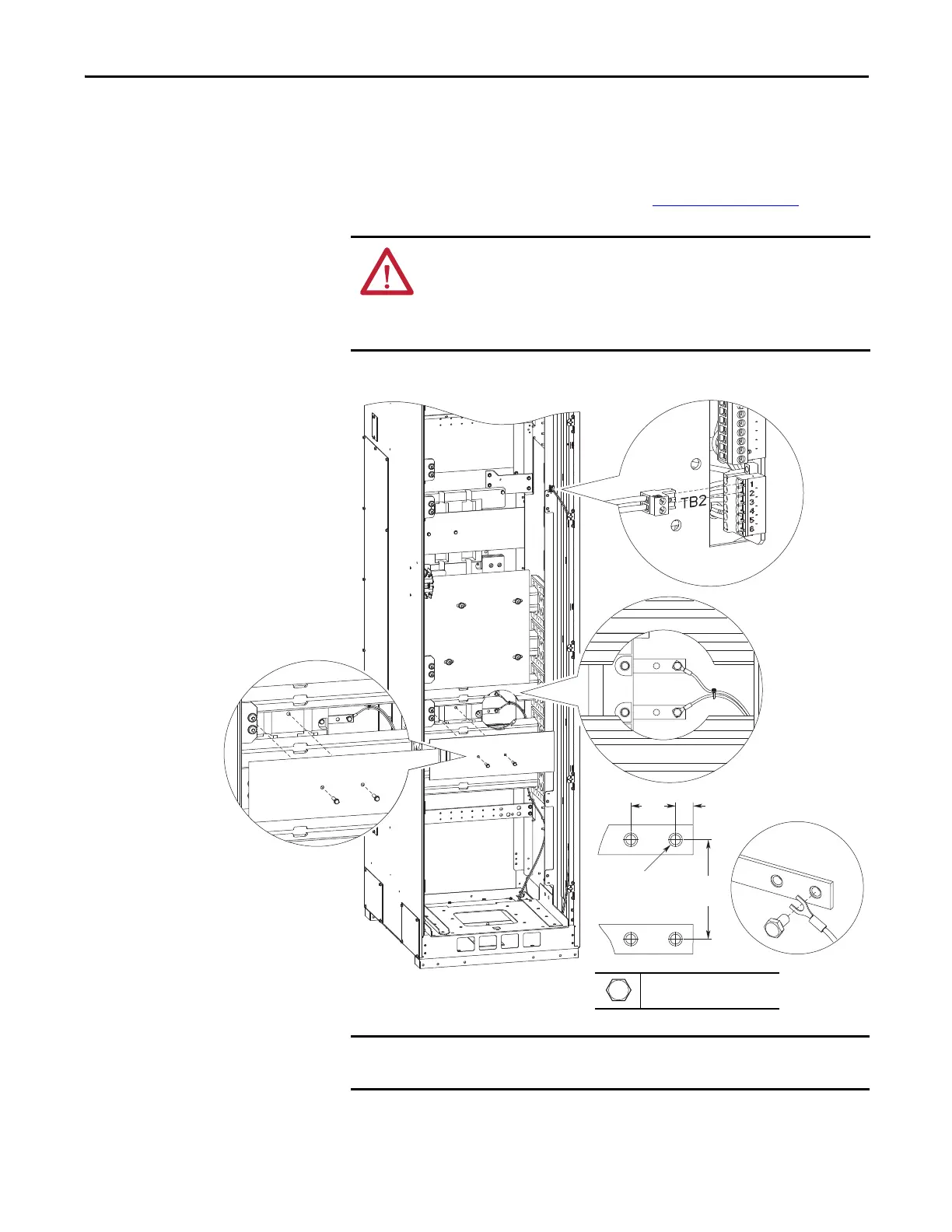
The user-supplied 120V AC UPS is connected to the lower 120V rail in the back
of the Common DC Input drive cabinet. The UPS rail is only installed when the
P30 UPS Control Bus option is selected. The rail is connected to TB2-1 and
TB2-2 on the Common DC Input drive control panel. To use 120V AC UPS
power, configure the TB5 jumpers as shown in Table 53 - on page 237
.
Figure 130 - UPS Connection Terminals - Floor Mount Frames 8…10
ATTENTION: To avoid an electric shock hazard when servicing the drive, a
means for Lockout/Tagout of an external 120V uninterruptible power supply
must be provided. Or the circuit breaker SW5 must be locked and tagged.
Locking and tagging the common bus precharge disconnect switch SW2 alone
does not provide sufficient protection when servicing the drive.
29.0
(1.1)
11.0
(0.4)
63.0
(2.5)
1/4-20
4X
7/16 in.
5.1 N•m (45.0 lb•in)
Hot
Neutral
The UPS wiring is internally wired through the DC input drive disconnect switch
SW2 ahead of the UPS terminal connections.

 Loading...


