Rockwell Automation Publication 750-IN001O-EN-P - October 2014 155
Power Wiring Chapter 4
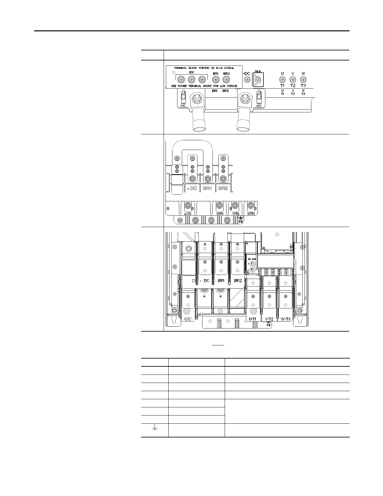
Wall Mount Frames 5…7
Common DC Input Power
Terminals
Table 11 - Common DC Input Terminal Designations
Frame Power Terminal Blocks
5
6
(1)
(1) Dynamic Brake Resistor Terminals are optional on Frame 6 and 7 drives: catalog number position 12.
Refer to Catalog Number Explanation on page 13
.
7
(1)
Terminal Description Notes
+DC DC Bus (+) DC Input Power
-DC DC Bus (–) DC Input Power
BR1 DC Brake (+) Dynamic Brake Resistor Connection (+)
BR2 DC Brake (–) Dynamic Brake Resistor Connection (–)
UU (T1) Motor Connections
(1)
(1) Important: Motors with NEMA MG1 Part 31.40.4.2 inverter grade insulation systems are recommended. If you intend to connect a
motor that is not rated inverter grade, refer to Wiring and Grounding Guidelines for Pulse Width Modulated (PWM) AC Drives,
publication DRIVES-IN001 for recommendations.
VV (T2)
WW (T3)
PE / PE Ground Terminating point to chassis ground for incoming DC line and motor
shield.

 Loading...


